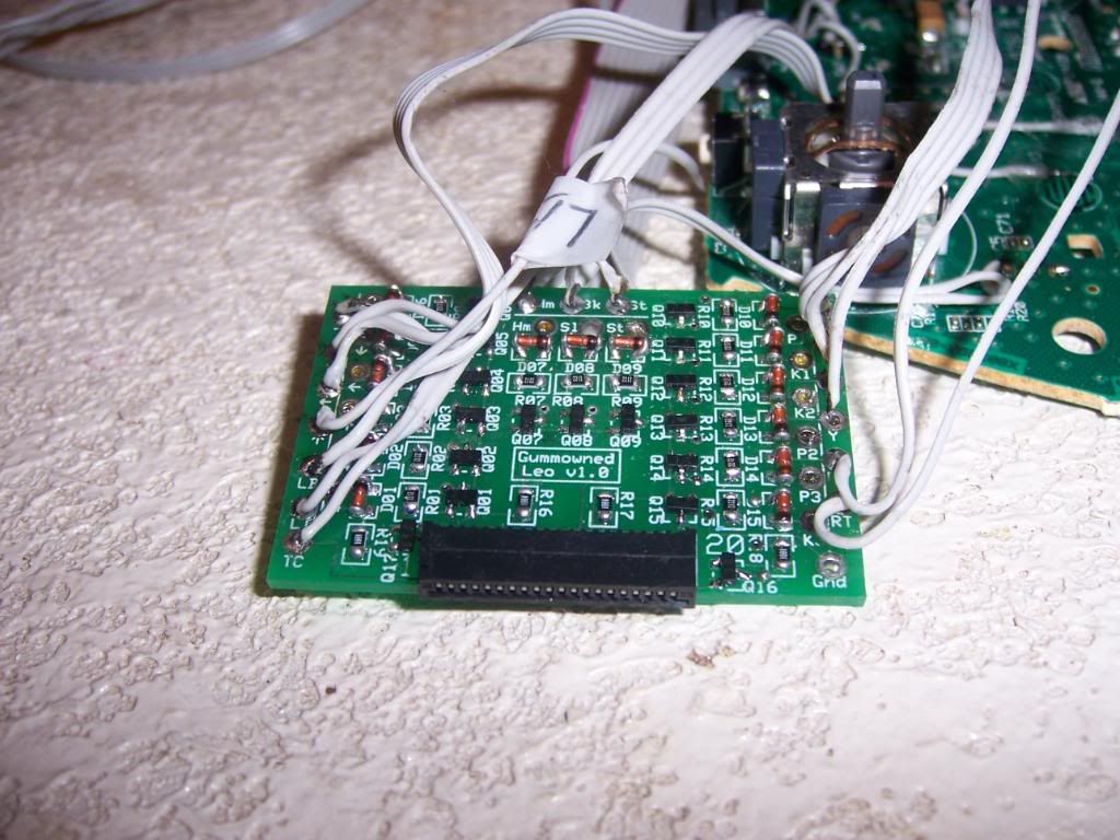
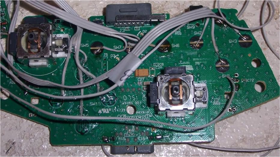
With the case FINALLY finished I needed to get back to soldering. The first task I tackled was soldering the wires from the 360 PCB to the leo. I started with the x/y/a/b button leads. I stripped and tinned the wire for each lead, then carefully soldered the individual leads to the appropriate spot labeled on the outer row of the leo board. I used the ‘third hand’ on the soldering iron holder to hold the leo in place while I added some flux on the solder point of the leo board. Then I inserted the lead into the solder point. A few moments with the soldering iron and the first of 16 wire leads was complete. I then repeated the process for the remainder of the button leads, the joystick leads, the bump and trigger leads, the trigger common line, and the home/back/guide leads. After what felt like an eternity, the board looked like this:
About 30+ points all on one board. Get comfy with your iron...
A smaller tip iron would have made this MUCH easier
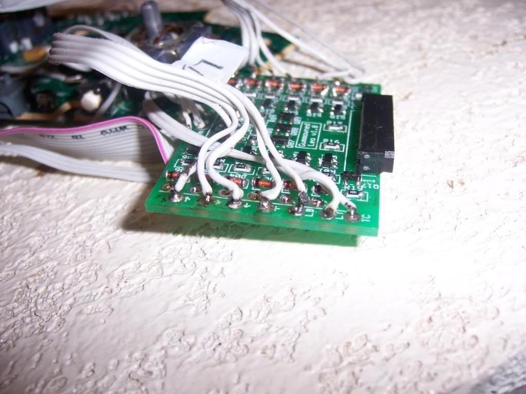
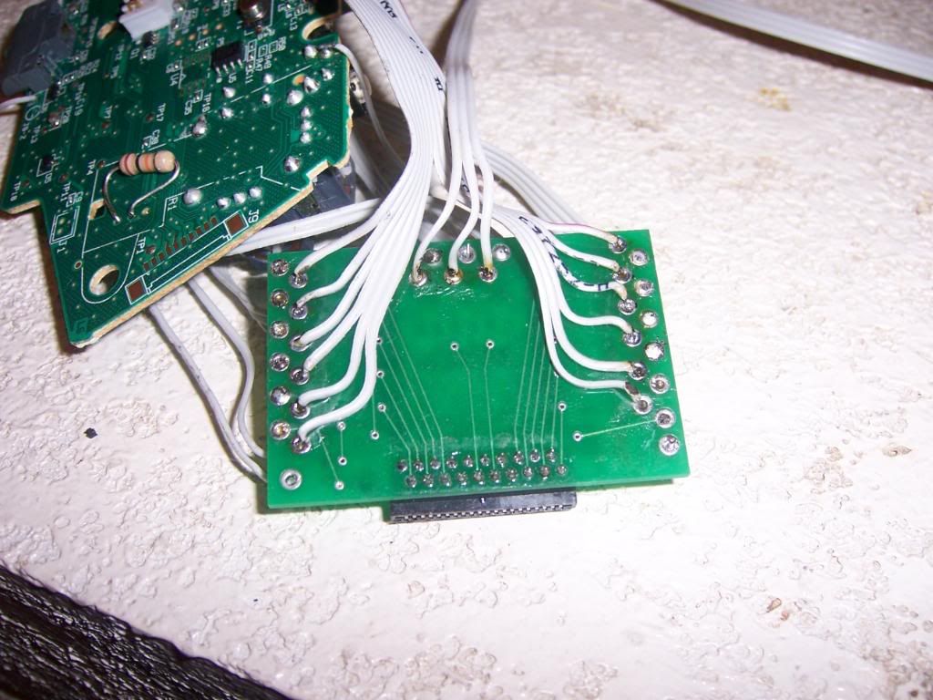
The next task was to solder leads from the leo to the buttons and joystick. I pulled 2 sections of wire from my IDE cable – one 12 wire section for the button and joystick row and a 3 wire section for the home/start/select row. Since I didn’t wan to take a chance on any of the wires touching or accidentally desoldering one of the 360 leads, I soldered the button leads from the bottom of the leo board. Before I started, I wrote down the order of the holes for the leo board on a sheet of paper, then wrote down which wire from the IDE cable section went with each one, starting with the #1 wire (marked with a red line). Then, I soldered the 15 leads just as before. I trimmed the button and joystick leads to length to fit a bit neater on the backside of the leo board (something I failed to do for the 360 leads, but I was learning as I went along, so sue me…)
Much neater, but took much more time to do it
The whole enchilada soldered together.
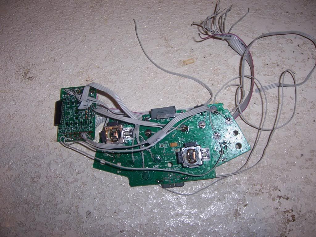
Instead of running the leads directly to the button and joystick switches, I decided to run them to a junction block. This would ease installation as I could vary the length of the leads I needed from the switches and make swapping out parts easier in the event anything needed to be replaced. The junction block would be secured to the right side of the case with 2 screws. But before I could worry about that, I had a few more wiring harness to make.
The first harness I decided to tackle would be for the joystick switches. I cut 4 pieces of wire, soldered on the QDs and snaked them through some cable sleeving. The harness would wrap around the base of the JLW and the exposed leads would go to the appropriate place on the junction block. Next up was the harness for the start/home/select buttons on the front of the case, which I did the same way as the joystick harness. After that, I had to make one long ground harness to tie the joystick, start/select/home buttons and the USB cable grounds together and run them to the power junction block on the other side of the case. By time I was finished that harness I didn’t want to solder anything for a while. Before calling it quits for the day, I wanted to see whether my soldering job on the leo worked. So I connected the harnesses to all the buttons and the joystick and ran them to the junction block, and connected the corresponding wires from the leo board to the junction block. I was smart enough to write down the order of the wires from the button harness so I didn't make a mistake and connect the jab button with the 3rd kick lead on the leo...
The wiring can't stop, won't stop...
Even though I didn’t have everything fully wired, I could still plug the battery to the sixaxis PCB and see if the buttons and stick connections were correct. Sure enough, the PS3 fired right up just it was supposed to. I did realize I had misread the labels on the leo board, so my up and down inputs were reversed. Since the iron was still plugged up, I made a quick swap of the wires on the leo board and called it a night.
While I was enduring my massive helping of FAIL with the bat top, I started work on getting the case painted. The first step was to cut the hole for the USB adaptor (which I forgot to do before I painted the first case, if you remember). The edge of the adaptor was much straighter and flatter than the last adaptor I used, so I wouldn’t have to work so hard on shaping the hole to make it fit.
Why is it so hard to find these things?
Once I figured out where I could put the adaptor inside the case where is wouldn’t interfere with anything, I traced the outline on the outside of the case. I then had a few options on how to proceed. I could have drilled a number of holes in the space I drew and used the chisel to clean away the rest of the waste, slowly shaping the hole to the correct size. Or, I could have whipped out the dremel, screwed on the cutting attachment and gone to town.
I have to justify buying this Dremel in the first place, so....
I put the case back in my project vice and set up the dremel. The multicutting bit made relatively quick work of cutting through the material. The only thing is, you really need a steady hand with this thing, which I didn’t have. The lines I cut were nowhere near straight. Had I clamped a straight edge guide to the case beforehand I probably would have fared a little better. No matter. A few more minutes with the wood file and the USB adaptor fit nice and snug. I made sure the adaptor was flush with the case then used some wood putty to make sure the edges were smooth and to fill in the little gaps I saw. Once the putty was dried, I taped up the adaptor plug and sanded it smooth, making sure to feather the edges and make the putty areas as level as possible. Once that was done I set up my paint area in the garage and sprayed on the primer. Once I had enough coats done, I sanded with 200 and 400 grit sandpaper, and wet sanded with 600 and 1000 grit sandpaper to make the primer nice and smooth. So far so good.
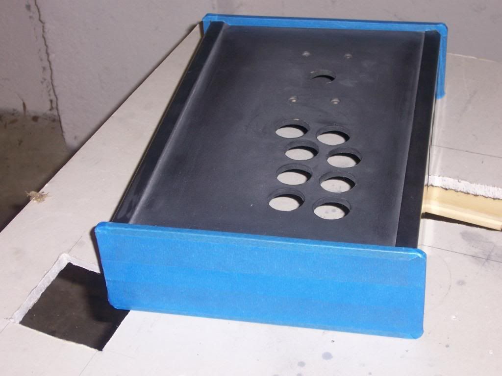
With the primer out of the way, it was time to mask off the case for painting. The front and back of the case were going to be painted metallic blue, while the sides were going to be painted yellow. In addition to the Rustoleom yellow that I was using (and failing) with the bat top, I had picked up a can of Duplicolor Metal Flake spray paint.
I used some 3M blue painter’s tape and masked the sides of the case and the edges that would be painted yellow.
Painter's tape is your friend. Believe it...
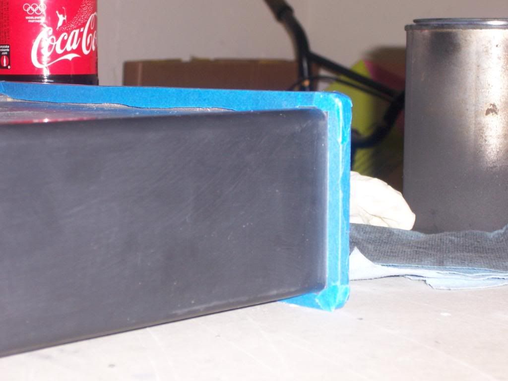
Very important to get the corners right. A Xacto knife helps
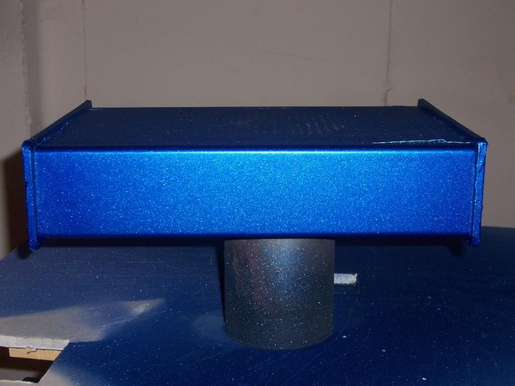
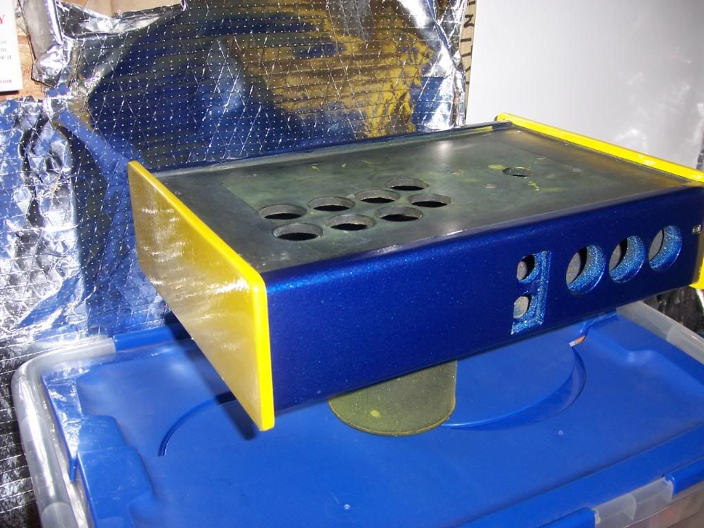
Afterward I wiped everything down with mineral spirits, set up the paint area in the garage and sprayed on about 4 coats of the metal flake, making sure to wear my respirator so as not to breathe in too many noxious chemicals. As the name suggests, the finish had a nice metallic look to it, without looking like someone tossed some glitter into a can of blue paint. Once the paint dried, I sanded it down with 200 and 400 grit sandpaper, cleaned it with the mineral spirits, and sprayed 4 more coats of paint. Once that was dry I repeated the sanding, but this time followed up by wet sanding the paint with 600, 1000, and 1500 grit sandpaper. I started to worry a bit when I noticed the blue was getting duller and duller. However, when I cleaned the paint off with mineral spirits, I noticed that the blue was nice and shiny before the spirits evaporated. So, I was pretty confident that once the clearcoat was applied that all would be alright. Once that was done, I let the case sit for a few days to make sure the paint was fully dry before proceeding.
Sparkly!
See why the tape was necessary?
Once I felt the paint was dry I removed the tape from the sides and applied it to the front and back of the case that had been painted. After I cleaned the sides with mineral spirits to make sure there was no paint residue, I sprayed on a few coats of the yellow paint and let it dry overnight. The next day, I sanded it down with 200 and 400 grit sandpaper, just as I did with the metallic flake. After giving it another mineral spirit wipe, I sprayed on another two light coats. When I went back to apply the next few light coats, to my bemusement the paint had started to wrinkle, just as it had with the bat top. This was becoming insane. So, once that paint dried, I sanded all the wrinkled paint off (which stated to come off in little balls of paint), and sanded the underlying finish smooth again. At this point I had just about run out of the Rustoleum, and really didn’t feel like getting another can, since it appeared I could only get one layer of paint on any given surface before wrinkling started to occur. So, against all recommendations and common sense, I grabbed the can of Krylon Fusion and sprayed that on top of the Rustoleum layer I managed to save (it’s usually suggested not to mix brands of paint, as they may react differently with each other). Less than 10 minutes later, I had a runny, wrinkled and ugly mess. So much FAIL, so little time…
I decided to leave the whole spray paint thing alone and go down another path. The weather was colder, the paint smell hung around in the garage longer than I wanted, I still had overspray I had to clean off my wife’s car, and so far the majority of my attempts at using spray paint had ended in failure. So, I started to look for a pint of yellow paint to brush on the case. I figured since I was going to wet sand the paint anyway, I wouldn’t really have to worry about brush marks showing up in the paint finish. Besides, I would be using a foam roller to minimize any applicator marks. Before I went to the store I went online to try to figure out what was going wrong with the spray paint. It worked fine when I sprayed the lacquer for my first case. This time, not so much. In the FAQ section on the Duplicolor site I came across this little nugget:
Q. What is a re-coat window? A. Re-coat windows apply to enamel paints and refers to the time period during which a second coat maybe applied. After spraying the first coat of an enamel, a second coat must be applied with in 1 – 2 hours or wait 5 days for the coating to cure. The paint may wrinkle or lift when resprayed during this curing period. Lacquers do not have a “re-coat window.” Subsequent coats of Lacquer can be applied over a Lacquer finish without wrinkling or lifting due to a “re-coat window”.
This sounded vaguely familiar. Could it be because I used the same information when I wrote my mirror finish paint guide on my first build?
One of the advantages of lacquer paint is that it dries more quickly than enamel and does not have a re-coat window (a time when a subsequent coat must be reapplied). With lacquer, you can spray the next coat once it is dry. With an enamel, you generally have a 1-2 hour time period in which you must spray the next coat, or you will need to wait for the paint to cure, which can take 3-5 days, depending on your brand of paint. Check the instructions on your paint can and be sure to follow those.
I could have worn this around for a week...
This is what I get for not following what I wrote. All that fail could have been avoided. I wasted about a month trying to get the bat top painted, at least a week on the case, all because I didn’t read. Sometimes, I’m not so bright, I tell you…
In any event, the case had to get finished, and I was determined to get it right, come hell or high water. So, back to Lowes I went. This time I picked up a pint of Rustoleum Safety Yellow enamel paint, a foam touch up roller kit (no need for a 4 inch roller on such a small case), a can of paint thinner and some 3M stripping pads. When I got home, I poured a little paint thinner on the stripping pad and started sanding down the yellow paint. My goal was to remove as much of the yellow enamel spray paint as I could, then use some more primer as a base for the new can of paint. With a bit of elbow grease, I was actually able to sand down to the original coat of primer, which looked just fine. I went over the primer with some 400 grit sandpaper to remove any possible residue and wiped it down with mineral spirits. Then, I cracked open the can of paint. The instructions said the paint would be dry to the touch within 3-4 hours, could be handled in 9 hours, and could be recoated in 24 hours. I poured some paint in the roller tray then rolled the paint on the case, making sure to get a nice even layer of paint down. There were a few small air bubbles on the surface, which I went back over after about 15 minutes, but I knew when the paint dried they would go away. Sure enough, the next day had a nice, smooth glossy finish. I sanded the paint down with the 220 and 400 grit paper, cleaned with the mineral spirits, and put rolled on a second of paint. Same results the next day – a nice glossy finish with NO WRINKLES!!! Amazing what happens when you read. Over the next 2 days I put 2 more coats of paint on to make sure I had a nice layer of paint. After the 4th coat, I sanded with 220 and 400 grit paper, then wet sanded with 600, 1000 and 1500 grit sandpaper.
That took soooooo much longer than it should have
I now had to make a decision on the clearcoat for the case. Since my results with spray anything had been less than stellar, to put it mildly, I did not want to use the clear enamel I had originally bought. Instead, I opted to buy a can of Minwax Polycrylic, which is a water based polyurethane top coat. Poly is often used as a protective clearcoat on wood, giving the finish a nice shine. Since the polycrylic is water based, there would be less chance of it reacting with the painted case, and easier cleanup.Of course, nothing had gone according to plan on painting the case, and this would be no exception. The first coat of poly I put on the yellow paint caused the same wrinkling that had occurred with everything else. Sadly, part of me wasn't even surprised. I had actually come to expect it by now. This time, I couldn’t quite understand why. Being water based, it shouldn’t have reacted as badly with the finish (the poly over the blue sparkle paint would have no problem). Plus, the can of Rustoleum said you could recoat within 24 hours. Apparently, that didn’t apply to top coating with another product. After all, I was still was an enamel paint, which requires a cure time. I was determined to lick this once and for all. So, I wiped off the poly as best I could before it completely dried, sanded out the wrinkles once again and painted the yellow sides one last time. Once it dried, I sanded everything up to 1500 grit again and set the box aside for a week. I wanted to make sure the paint had enough time to cure before I attempted to do anything else.
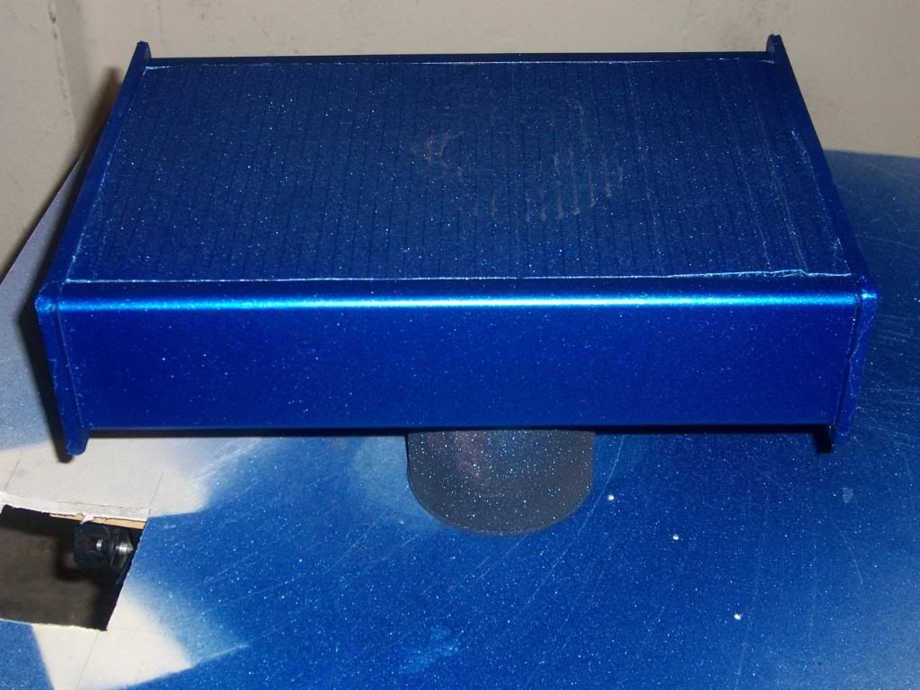
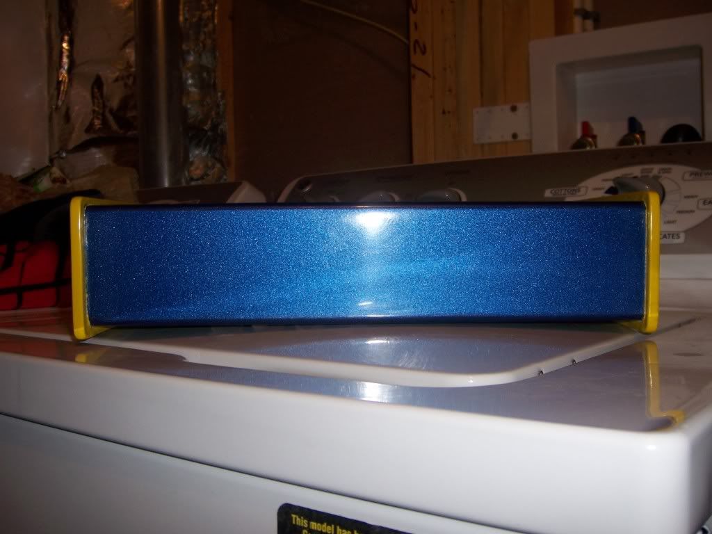
After 7 days it was time to get back to work. Using a natural bristle brush, I went back over the case with the polycrylic. This time it went on with no problems at all. The poly looks like thin milk when brushed on, but once it sets up it dries crystal clear in about 2 hours. After it was dry, I sanded the poly down with 220 grit sandpaper, wiped it clean with mineral spirits, and recoat. It’s recommended to put on at least 3 coats of polycrylic to your project. I decided to go with 6. Since I was going to wet sand the poly to a mirror shine, I wanted to make sure I had enough layers down to make sure I didn’t sand all the way down to the paint by accident.
Glossy!
Just wait 'till the hard work is done...
After all the coats of poly were applied, I went thru my sanding and wet sanding routine all the way up to 2000 grit sandpaper. With each successive grit of paper the surface got smoother and smoother, while the finish looked duller and duller. After the rubbing compound went on, all was right with the world, as both the blue sparkle paint and the yellow paint had that nice, glassy mirror finish. I followed up with the polishing compound and a coat of glaze for that extra bit of shine. After weeks of failure, finally I had the sweet taste of victory. But my celebration couldn’t last too long, as I had to get back to soldering. And there was a WHOLE lot of soldering to be done. Time to get to it…
The line between success and failure in any project is planning. Any idea can look good on paper, but unless you have a good plan and are willing to roll up your sleeves and make it work, you’ll end up with a large helping of FAIL. With that in mind, I needed to figure out how to get my pièce de résistance from a good idea to reality.
LEDs (Light Emitting Diodes if you didn’t know) are wonderful things. They’re small, light, long lasting, use very little power, and can be bright as the sun (ever looked into a LED flashlight? Don’t…). People have been using LEDs on projects for years, ranging from useful, to quirky, to head-scratchingly strange to extremely nerdy. Don’t believe me? Just check this link and get back to me: 10 Stuningly Nerdy LED Projects That Are Real... Anyway, the inherent geekiness of building your own fightstick made it inevitable for people to figure out ways to cram LEDs into their custom projects. These can range from simple, such as having the lights on all the time, to slightly more involved, like having the buttons light up when you press them, to even more involved, like having 2 different colored LEDs in each button, to something much more extreme, such as designing your own custom LED board and controller to program colors, button flashes, and more. Then you have people that make dual mod, LED encrusted, robotic coffee tables like this:
Needless to say, my mod was going to be much less involved than that. That said, there was still a good amount of work that needed to be done to get this to work. First of all, you need to buy the buttons. Both Happ and Seimitsu carry translucent buttons in a variety of colors to suit your artistic need. You can even mix and match the plungers and bezels if you like for a more custom look. Next you need the LEDs. You can find these in a variety of colors, wattages and levels of brightness. You also need to purchase the correct resistors to ensure the lights don’t burn out or draw too much current from your power source. Next you have to figure out how to attach the LEDs to the buttons. Some people have run the leads for the LED in between the slot where the plunger and the bezel meet. It works, but that runs the risk of pinching the lead in between the two pieces and shorting it out. Others have taken a tiny finger drill and made holes in the bottom of the bezel, and run the wires through there, like so:
That takes patience and a steady hand
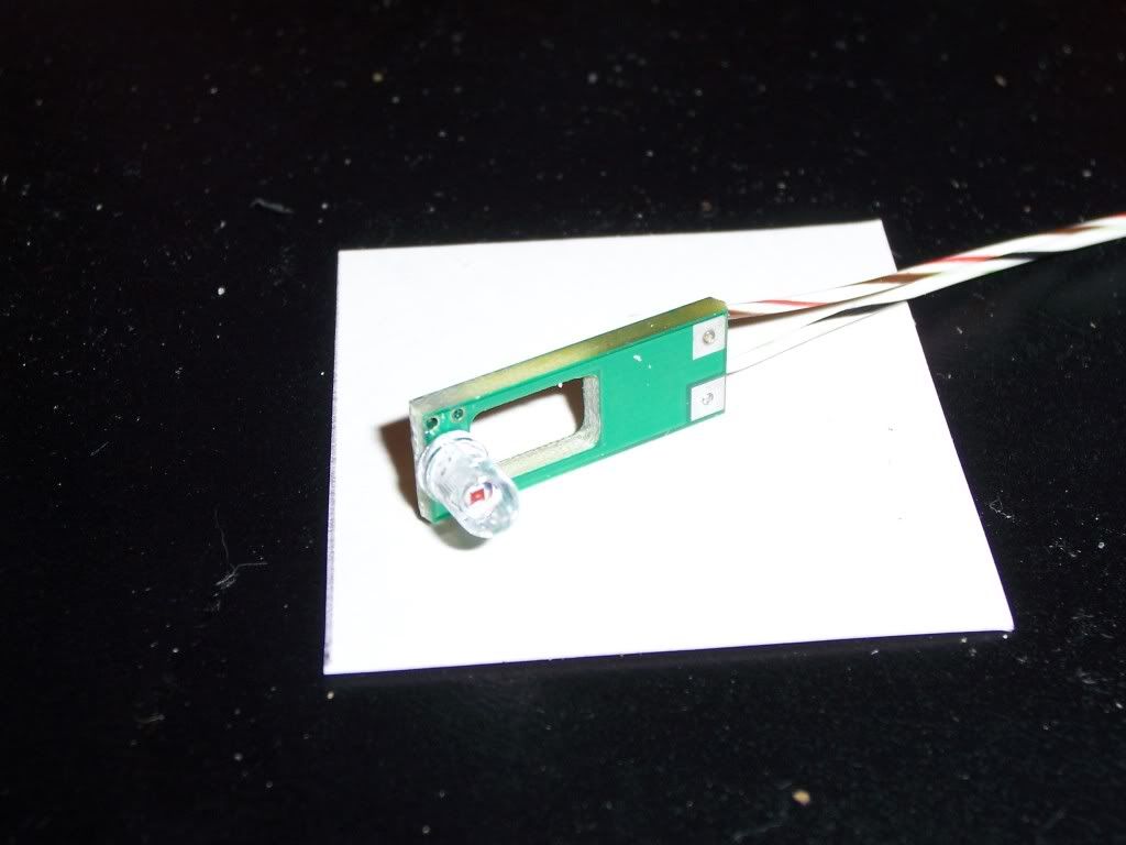
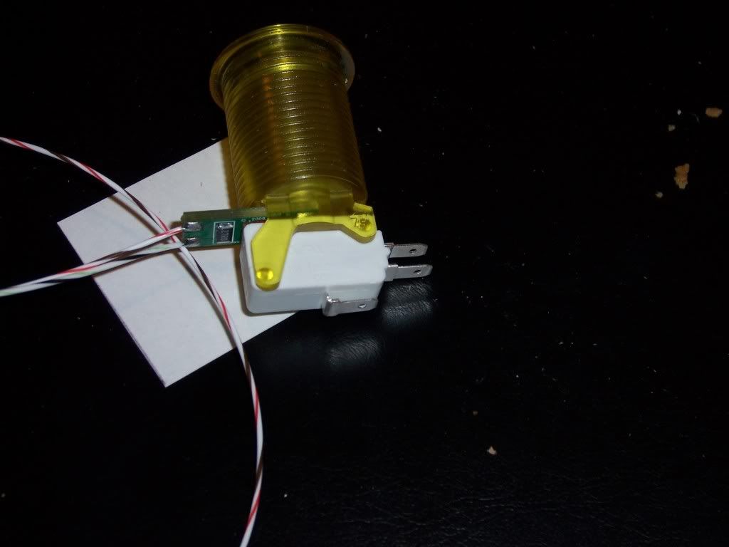
After all of that, you still need to figure out how to wire the LEDs to come on, which I’ll get to in a bit. As far as all that other craziness, I decided to take a slightly different path. Astute readers may remember I picked up the buttons from Groovy Game Gear. These buttons are designed to be used in MAME (Multiple Arcade Machine Emulator) setups (for a peek down that rabbit hole, start here). The nice thing about these buttons is that the LEDs come soldered to their own little electronic board with the appropriate resistor. The board then fits between the button and the cherry microswitch, and the LED fits into the predrilled hole at the bottom of the button. They also have nice, long leads soldered to the board to assist in wiring everything up.
Averything in one neat package
Doesn't take up more room than the button itself
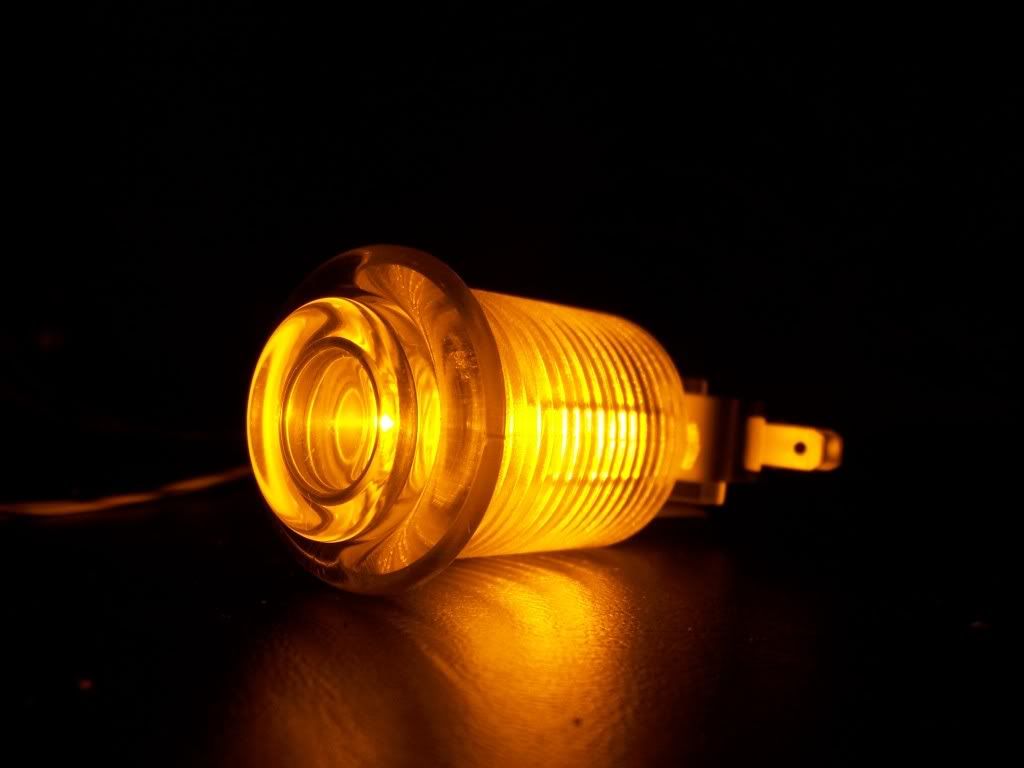
The LEDs are set up to take 5 volts of current (the amount coming from the USB terminal). However, since I’m doing a wireless stick, my available voltage will be limited to what the lipo battery puts out: 3.7 volts. On the one hand, this will make the LEDs slightly dimmer than they could be. On the other hand, I wouldn’t have to worry about burning them out by supplying too much power to them. So, I took one of the assembled buttons and ran the anode and cathode (positive and negative) leads from the LED board straight to the battery to see how it would look:
Pretty lights.....
The light was bright enough to be noticeable, but not too bright to be a distraction while playing. Considering the battery was only partially charged, I felt pretty confident the lighting would work well for this project.
With that out of the way it was time to figure out how to wire everything to make it work. Reading over the boards on SRK I came across a couple of methods to making the lights work. The easiest way by far was discovered by beneco74 (another electrical genius without whom I would never have finished this), which you can read in detail here. The wiring diagram looks something like this:
In case both of those are still Greek to you, I’ll try to put this in layman’s terms. For this project, the positive lead (anode) of the LEDs all get daisy chained together and wired to the positive side of the battery (or the 5v from the USB, if you were doing a wired setup). Each negative lead (cathode) of the LEDs are wired to their corresponding button signal wire (there would be two wires connected to the button terminal – one for the LED anode and one for the wire from the PCB). The ground wires for the buttons would then be daisy chained as normal. What ends up happening is the LEDs are wired in series along with the buttons, When the button is pressed, no only does it complete the circuit with the PCB, but it also completes the circuit with the LED, switching the power on and off when the buttons are pressed. If all that still doesn’t make sense, just trust me, it works!
With the theory out of the way, I now had to actually get everything wired up. I installed all of the buttons with the LED boards and switches in place so I could figure out which direction I needed to turn the buttons to make routing the wires easier. One concern I had was how this would work if I ever needed to replace any of the components (LED board, bad switch, buttons, etc). Instead of soldering the cathodes directly to the switch or directly to the wiring harness, I decided to use female quick disconnects on all the LED cathodes. I could then connect 2 wires to each quick disconnect for the signal harness: one that would run from the button to the leo PCB, and a shorter wire with a male quick disconnect to connect to the female quick disconnect on the LED cathode. Initially, I decided to run all of the anodes to a junction block, wiring 4 to each terminal and using a jumper wire to connect all 8 together, then using another jumper wire to connect them to the battery. All I would need then would be to make a ground chain for the switches and the lights should work.
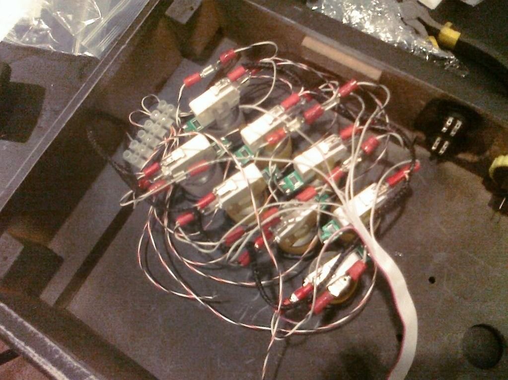
Setting up the cathodes was pretty simple. I cut each of the cathode leads on the LED boards down to about an inch and soldered a female .187” connector to it. Quick disconnects are made so you can simply crimp the ends to the wire, eliminating the need to solder them. But, I wanted to make sure the connection wouldn’t come loose after I delivered the finished product. After that, I decided to tackle the ground chain. I took a piece of the leftover wire from the cathode lead and soldered on a female .187” connector. I slid the other end through a thin piece of cable sleeving I had, then connected it to the ground on the switch. Next I stretched the sleeved cable over to the next switch to figure out how long the wire needed to be in the chain. Once I determined the length needed, I pulled the wire thru the sleeving and trimmed it close to the switch. Next I took another piece of wire, slid one end back thru the cable sleeving and twisted the other end together with the first piece of wire. Then I soldered the connector on the two wired and connected it to the ground of the switch. I then repeated the tedious process for the next 6 buttons. The last wire in the chain I left free, since that would be connected with the battery ground. With that finished, it was time to work on the signal harness. First, I pulled off one long strand of wire from the IDE cable and cut it into 8 pieces, each about 1 ½ inches long, and soldered a male .187” connector to each. Next, I grabbed some more IDE cable and pulled off a long 8 wire section. I split one end of the cable about ¼ of the way down the middle, with 4 wires on each side. Starting with the 2 buttons closest to the edge of the case, I pulled one wire free from each side of the IDE cable and stripped the ends. I twisted one of the wires with the male connector on each end of the wires from the IDE ribbon. Then I soldered on a female connector to each. Now I could connect the harness to the signal tab on the switch and connect the male and female connectors of the cathodes together. Once I finished those 2 buttons, I pulled off 2 more strands from the IDE cable and trimmed them close to the set of buttons and repeated the process until all 8 buttons were wired. To make sure that all my connectors were soldered properly, I connected the anodes to a junction block as I described earlier, and connected the ground chain to another spot on the junction block. I then ran 2 wires from the junction block to the battery.
That is a LOT of wire. And I'm just getting started...
To my surprise and glee, the buttons worked as promised, lighting up nicely whenever the button was pressed, even if more than one button was pressed at a time. Since the wires looked a bit ungainly I ran the anode leads through another piece of cable sleeving, allowing me to route the leads closer to the buttons and making everything look neater. The whole process took much longer than I anticipated, but it was nice to know that my plan would actually work. That said, there was still an enormous amount of soldering and wiring that I had to do before I was any where close to being done. I still had to solder the 360 PCB to the leo, solder the signal wire harness from the buttons to the leo, solder and wire signal harnesses and ground chains for both the joystick and the start/select/home buttons, solder wires from the USB points from both the 360 PCB and the PS3 PCB to the switches, and wire up a USB cable from the switches to the USB adaptor, which still hadn’t come in the mail. Daunting, to say the least. However, the Vikings/Cowboys game was on, and my red plastic cup was in need of an adult beverage. So I called it a day and watched Favre do his rendition of ‘Pants On The Ground’ …
I decided to take a break from the soldering for a while and focus on painting. Since the weather getting even colder, I figured that it would be a good idea to get the paint finished, making sure it would dry and that I wouldn’t be spending too many nights in a chilly garage. Since I thought I had learned from my mistakes from the first case, painting this one should be pretty simple. Little did I know how many ‘L’s I would be taking…
As mentioned, the MadCatz MvC stick has a yellow and white button scheme, with a yellow ball top. Since I was putting my own spin on it, I too was going with yellow and white (clear) happ parts with a bat top, just like the American style arcade cabinets. While the JLW joystick does come with a bat top handle, they only come in black, white, blue and red. No problem, I say to myself, I can just paint one. I could even give it a nice shiny finish just like the balltop with a little work (although in retrospect that would probably be super slippery). My only concern was I would be painting plastic, which can be finicky as far as paint adhesion if you don’t do it right. The last thing I wanted would be is the paint would flake off or stain your hands over time. My first choice for paint would be the new Rustoleum Universal paint, which is supposed to adhere to almost any surface.
The only problem is, it seemed no store in my area had it at the time. Home Depot, Lowes, AutoZone, Advance, Target, Walmart –all they had was black, white, silver, maybe a green. No yellow. However, I came across some Valspar Plastic paint, formulated specifically for plastic (duh), with no sanding required.
Not in red, of course...
So I figured I’d buy a can and give it a try. Once I got home I set up my paint area in the garage again. I had to figure out how to hold the bat top steady while painting it. I used a wooden dowel that was close to the diameter of the threads in the bat top, sanded it down slightly and screwed it in. I then drilled a hole in a scrap block of wood I had and placed the other end of the dowel there. Now I had a makeshift stand where I could spray the entire top at one time. I cracked the garage door for some air, applied 2 coats as suggested, and waited for it to dry. After a few hours, it was evident this wasn’t going to work. The paint had started to run and drip off the bat top, leaving the paint too thin on the top and pooling heavily on the bottom. If the weather was a bit warmer, the paint may have dried before it started to run, but this wouldn’t be the case for the middle of winter. So, one can of paint wasted, one ‘L’ for me. I soaked the bat top in some latex paint remover for a day and peeled and scraped the paint completely off. After washing it with cold water and wiping it down with mineral spirits, I let it dry while I figured out what to try next.
I decided I’d try to paint the bat top with a good coat of primer, followed by the yellow paint and some clearcoat for protection and shine. If the primer would stick to the bat top, the paint would bond to the primer and reduce the chance of flaking off. Plus, I could perfectly match the bat top with the color of the case, since I’d be using the same can of paint. So, I went back to the store for a can of Rustoleum.
To aid primer adhesion, I lightly scuffed the bat top with some sandpaper. Once I wiped the residue, I set the bat top on my stand and painted 3 coats of primer. Once it was dry, I wet sanded it with 400 and 600 grit sandpaper until the finish was smooth. Next, I sprayed on the yellow paint. After 5 coats, I had a nice even layer of paint built up and a garage full of fumes. I decided to quit for the day and let it dry overnight. When I got home from work the next evening I wet sanded the yellow paint with 400, 600 and 1000 grit sandpaper. The finish was now nice and smooth, with a rubbery, grippy feel to it. I let it dry overnight with the intent on spraying the clearcoat the next day after work. I was eager to see how this would turn out, since things seemed to be going well so far. So when I got home, I changed my work clothes and hit the garage with the can of clearcoat in my hand. However, not 5 minutes after I sprayed the first coat I knew something was wrong. The yellow paint started to wrinkle as if someone balled up a piece of Saran Wrap. I looked at the can I sprayed and confirmed my worst fear: I had picked up the lacquer clearcoat I had used on my first stick, not the enamel clearcoat I had bought for this project. As a result, he solvent in the lacquer was eating through the enamel paint. ‘L’ number 2 for me. Dejected, I tossed the ruined mess in a container with some paint thinner, determined to clean it off and try again in a few days.
Bat top painting, take 3. All goes just like before. Clean and scuff the bat top. Spray 3-4 coats of primer. Let dry overnight. Wet sand. Spray 5 or so coats of yellow paint. Let dry overnight. Wet sand. This time, I made sure the lacquer was faaaaaaaaar away from me and double checked the label to make sure I had the enamel clearcoat. The first coat of clear seemed to go on ok, but after I the second coat the yellow paint started to take on a textured look not unlike an orange. The paint wasn’t wrinkling as badly as it did with the lacquer, but it definitely wasn’t smooth, and sanding wasn’t going to help. To be honest, the texture looked pretty cool (almost like the texture and look the plastic on a happ joystick has), but it wasn’t uniform, so leaving it that way wasn’t an option. I once again soaked the bat top in a fresh batch of paint thinner as I accepted my third ‘L’ of the project, contemplating what went wrong this time. I thought the enamel wouldn’t react to itself like it would react to the lacquer, so I didn’t think that was a problem. I started to wonder whether or not the paint was fully dry from the wetsanding, and if not would that have been the cause of the wrinkling paint. So, after cleaning the paint off the third time I went through the entire process again. After I wetsanded, I decided to wait 3 days before trying the clearcoat. After the third day, I noticed I had sanded a few spots thinner than I liked, so I decided to spray on a few more coats of yellow. Guess what happened? Yep, wrinkling paint. This was staring to get old…
At this point I decided it was time to try something else. Since I couldn’t find the yellow Rustoleum Universal paint, I did some reading on Krylon Fusion paint, which is supposed to be somewhat similar to the Rustoleum. It’s claim to fame is that it bonds to plastic, dries to the touch in 15 minutes, requires no sanding or priming, and is workable within an hour. Others on the SRK forums have had decent success repainting their MadCatz SE cases, so I figured I would give it a try. I went down to Walmart and picked up a can.
This stuff should work, right?
To make a long story short, history repeated itself. The paint came out much like the Valspar paint for plastic, but runnier. That’s 5 tries and 5 ‘L’s. All for aesthetic purposes.
Now I’m at a loss. Every time I tried to paint this bat top has ended in failure for one reason or another. Not only has this wasted time and money, but the spray paint was starting to leave a dusty film on some things in the garage, like my wife’s car. Fortunately, a cloth and mineral spirits made for relatively easy cleanup. That and the fact she hadn’t washed her car in months made the yellow film unnoticeable to the untrained eye. While racking my brain on what to do next, I called my mother for advice. Her favorite color is purple, and she has been known to dye everything purple, from shoes to bags to cowboy hats (and I wish I was lying…). She mentioned she used spray dye that she found at the shoe repair shop. Unfortunately, they didn’t carry yellow. After a few other suggestions that I told her wouldn’t work, she suggested dyeing the piece with Rit. This sounded like a great idea. People had been dyeing their RC parts in Rit for years to get that custom color to make their car stand out. Why I hadn’t thought of that is beyond me. Then again, this wouldn’t be the first or last time I’d not think of something on this project.
So, back to the store I went. I picked up a box of golden yellow Rit dye. I also ordered a white bat top from LizardLick. I figured the white would take on the dye better than the black bat top I was working with. Don’t ask why I didn’t get a white one in the first place, because I have no clue. Once I had everything together I grabbed my crock pot I use to clean the exhaust pipes on my RC (another post for another time) and mixed the dye according to the directions. Using the dowel I had for painting, I placed the bat top in the pot of dye, checking it just as directed to make sure it didn’t get too dark. 30 seconds. 60 seconds. 90 seconds. Two minutes. Each time I checked, it seemed the dye barely did anything to the bat top. Once I rinsed as directed, what little tint was washed off completely. I tried leaving it in the dye for 10 minutes before pulling it and rinsing. Same effect. Next, I added more dye, figuring I may need a higher concentration of dye on this particular plastic. After 20 minutes, the dye had just barely started to have any effect. The only other thing I could thing of is that my crock pot wasn’t heating the dye up enough, even on high. As a last ditch effort, I took the ceramic bowl with the dye out of the heating element of the crock pot and took it upstairs to the kitchen. Making sure not to splash it anywhere, lest my wife kill me, I placed it on the stove and brought the dye to a rolling boil, then let it simmer for 2 hours after that. The result? You all know what happened, go on, you can say it…’L’. Is that number 6? I’m starting to lose count.
So, plastic paint wasn’t working. Enamel paint wasn’t working. Powdered dye wasn’t working. What else is left to try? Vinyl dye. The dye is formulated to seep into the vinyl or plastic and bond to the material, rather than sticking to the surface like paint. People often use the dye when restoring or customizing their cars, dying the dashboards or seats. This sounded like just the ticket to getting the bat top painted once and for all
Man, this had better work....
However, finding it locally was futile. AutoZone, Advance Auto Parts, even the great bastion of cheesy car customization, Pep Boys- nobody carried yellow vinyl dye. You would think somebody would need it to paint the seats and dash of their 1997 Honda Civic DX bright yellow to go along with the 3 foot wing and 4 inch fart pipe, but no. So I ordered a can online and had it shipped to the house. Two days and $20 later, the paint arrived. One afternoon when the weather got above 40 degrees I took the bat top and painting stand outside, along with the switches I would be using, and sprayed on the dye. Per the directions, I sprayed 3 light coats on the parts, followed by a few heavier coats, all about 10-15 minutes apart. After about 6 or 7 coats I had a nice even coverage of yellow on the top and the switches. Afterward I brought the parts in and let them sit for a week per the instructions. Once everything was good and dry I used a bit of 15oo grit sandpaper to smooth out the edges, and then used some rubbing compound and polishing compound to bring out a nice shine.
Finally, the bat top was finished. Who would have thought that something so small would have taken so freakin’ long to get right? If I had started with the vinyl dye in the first place, I would have saved myself so much time and money. But without the dye being available locally, trying something else proved an extreme exercise in futility. I couldn’t figure out what was going wrong with the regular paint, which bugged me to no end (and I would have my Bill Engvall moment later on once I figured it out). To be fair, many have had great success with the Krylon Fusion line, and had it been a little warmer things may have worked out on the bat top. But at least I got it done for the sake of the project.
Just to show how funny life can be, I went in AutoZone a while after that to get supplies for my oil change. Just for giggles I walked down the paint aisle. A bright yellow can of Rustoleum Universal paint sat on the shelf, mocking me. Apparently, AutoZone decided to start carrying it AFTER I took my repeated ‘L’s. I didn’t know whether to laugh, cry, or knock all the paint off the shelf. Ah well, live and learn. There' sno telling whether that would have worked any better than the Krylon, and I don't really care to find out either at this point. Hopefully, after the huge helpings of FAIL that I had working on the bat top, painting the case should be much easier. Right?
Most of the modifications I needed to make to the case were done. It was now time to turn my attention to the most challenging part of the build: soldering. Since there is no plug and play solution for a 360 stick, there’s really no alternative. For those uninitiated, soldering is the process of joining 2 or more metal objects together, usually by melting metal filler (in this case solder) into the joint. With the pieces of metal touching each other, solder is melted with a soldering iron, which then cools and joins the two pieces. There are a number of resources online you can read up on to learn more on soldering and techniques, such as this here. Likewise, there’s always YouTube…
I have a Black & Decker soldering iron I bought some years ago for my r/c batteries. The nice thing about the iron was it came with 2 movable clamps to act as a ‘third hand’. That way, the board and/or wires could be held in place while I maneuvered the iron and solder. But I did need to pick up a few items from Radio Shack. I purchased some rosin core solder of 2 different thicknesses and some flux paste (which was pretty invaluable and highly recommended for soldering work like this). I also picked up some desoldering braid, which I would need to remove the necessary parts from the 360 pad. The braid would soak up the melted solder from the joint like a sponge, thereby freeing the parts from the joint. Alternatively, I could have bought a desoldering bulb, which is like a vacuum that sucks up the melted solder, or desoldering iron, which has the bulb and iron together making the process a one handed affair, but the braid was sufficient (and cost effective!).
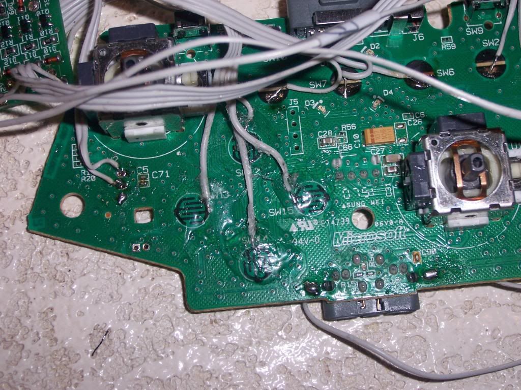
Once I got home I cracked open the 360 pad. I then carefully removed the pcb.
That's a lot of points to solder. Thanks Microsoft...
If you remember Gummowned’s walkthrough that I posted (and if you didn’t read my earlier post, you can find it here), there were 6 pieces that would need to be removed: the left and right triggers, the connectors for the rumble motors, and the positive and negative battery terminals. First, I plugged up the iron and let it get to the correct operating temperature. Using a brush, I dabbed a good amount of flux on the solder joint I needed to remove. Once the iron was hot, I placed the iron on one side of the joint, and the braid on the other side. After a few seconds, the flux smoked off and the solder melted, flowing into the braid. Once all of the solder was removed, the piece could be removed from the pcb. I made sure not to leave the iron on the joint for more than a few seconds. I started with the battery terminals, since the joint was not too small and there was less chance I’d screw it up. Once those came off and my confidence was up, I moved on to the connectors for the rumble motors. Those too came off with very little fuss. All that was left now were the analog triggers. The trigger pot was soldered to the pcb at 3 very small points. A few posts I had read mentioned that it was very easy to burn the contacts clean off the pcb if the iron was left on too long, damaging the board and rendering it almost useless. So I made sure to only hold the iron on the spot for 4-5 second max at a time. It slowed my progress a bit, but I was able to safely remove both of the pots and pull the trigger assemblies off with no fuss. All that was left was to use my Exacto knife and scratch off the black coating on the pads I needed to solder wires to.
All clear. But not for long
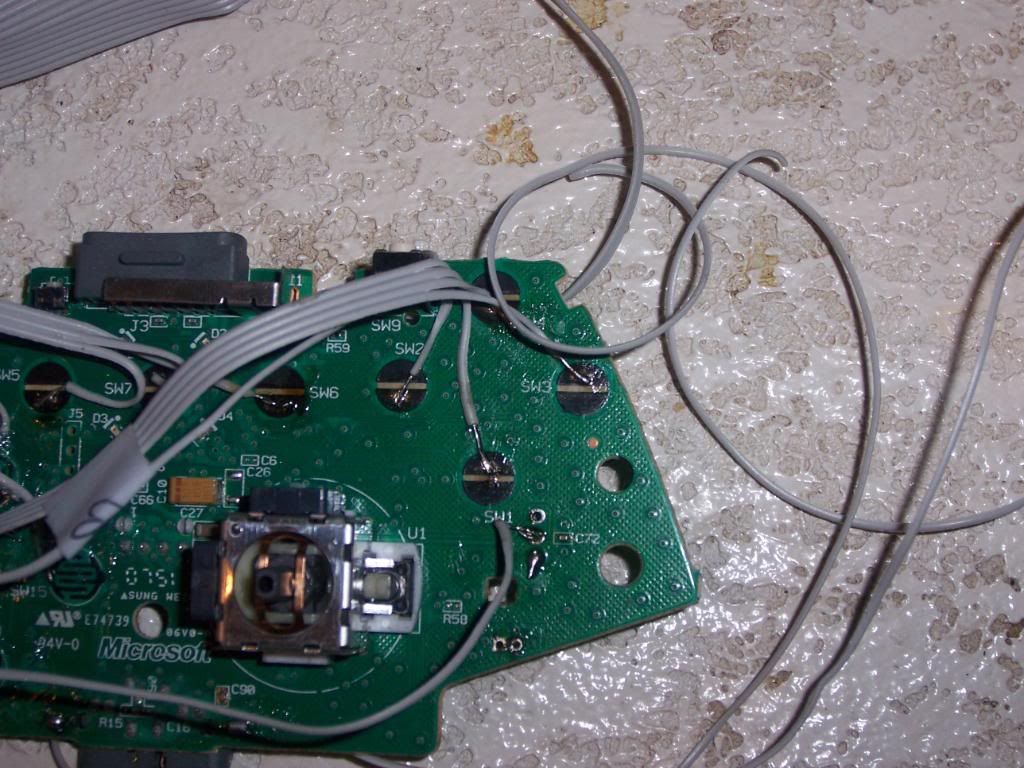
Now I was ready to solder the wires to the pcb. Since the contact points on the pcb were quite small, I wanted a small gauge wire to connect everything. The solid 22 gauge wire I used on the last stick looked like it would be too big for this application. Some stranded wire 26 gauge or smaller looked like it would do the trick, but the Radio Shack in the area didn't seem to have anything that small. Fortunately I did have some IDE cables from an old computer laying around. The wires were 28 gauge, and the flat ribbon made it easy to either keep the wires neatly together or pull individual strands and cut them to length. I broke the wiring up into sections. First, I pulled a 4 wire section from the IDE ribbon for the a/y/a/b buttons on the PCB. I stripped a bit of the wire, dipped them in the flux, then heated the soldering iron and tinned the ends of teh wires, so they had a nice coating of solder on them. Next, I liberally brushed flux on each of the contacts on the pcb. using the 'third hand' on the iron, I held the board with one clip while the other held the wire on the contact. I then heated up the contact and wire, adding a small dab of soler to ensure the joint stayed. Once it cooled, I tugged it slightly to make sure the wire would hold. Once done, I repeated the process with teh other 3 buttons. After they were all soldered, I placed wire labels on the other end of the wires so I would know which wire goes where when it was time to wire up the leo board. I repeated the whole process with the home/back/guide buttons and the directional pad. Since the contact points for the directional pads were so small, I placed a dab of shoe goo on each of the wires once the joint had set to make sure the wires didn't get pulled from the contacts. Using individual strands, I soldered and labeled the left and right bumps and the positive and negative battery terminals.
These contacts were easy...
...these, not so much. The contacts are tiny....
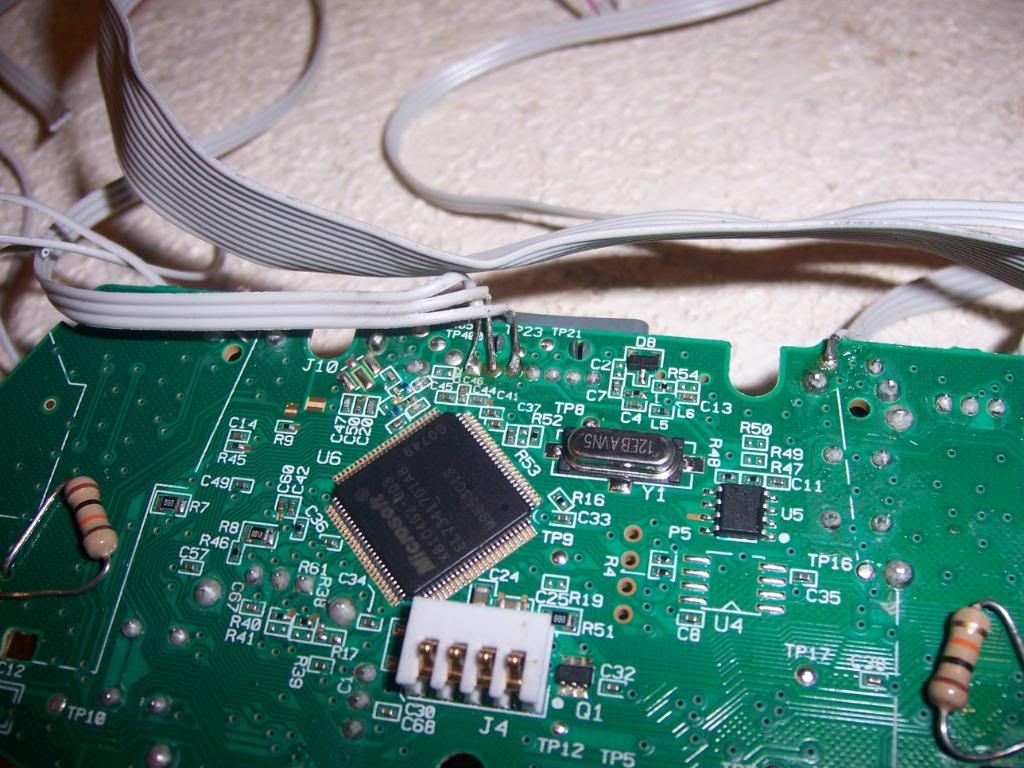
The triggers needed some special attention. In order to have them work properly, I needed to solder a 10k resistor to 2 contact points for each trigger. In addition to soldering the wire to the trigger contact point, I would need to solder an additional wire to the one of the contact points for the trigger common line (both triggers had a contact point for the common line; I just needed to tap into one). I bent the resistor into a horseshoe shape and ran the leads inside the contact points on the pcb. After they were soldered to the points, I trimmed the excess leads on the back of the pcb. With the resistors in place I then soldered the signal and common line wires to the pcb.
You can see the resistors and the USB connections here
The last bit that needed to be soldered to the pcb were the wires for the usb cable. Looking at the pinout guide, I determined where the 5v (power) , D+ and D- (data) lines were for the usb. There is also a ground line, but since I had tapped into the ground (negative battery terminal) for the pcb already, I wouldn't have to worry about that. Since those points already had solder on them, this was a (relatively) simple task of heating he existing solder while the new wire was touching it, allowing the solder to melt and cool with the new wire attached. Since the points were small and close together, I took my time and made sure there was no solder that may have run over to another point on the board. At long last, the 360 pcb was 'padhacked' and ready to be connected to the leo board. Much more soldering was yet to come.
If only this was all I had to solder. But no, there is MUCH more...
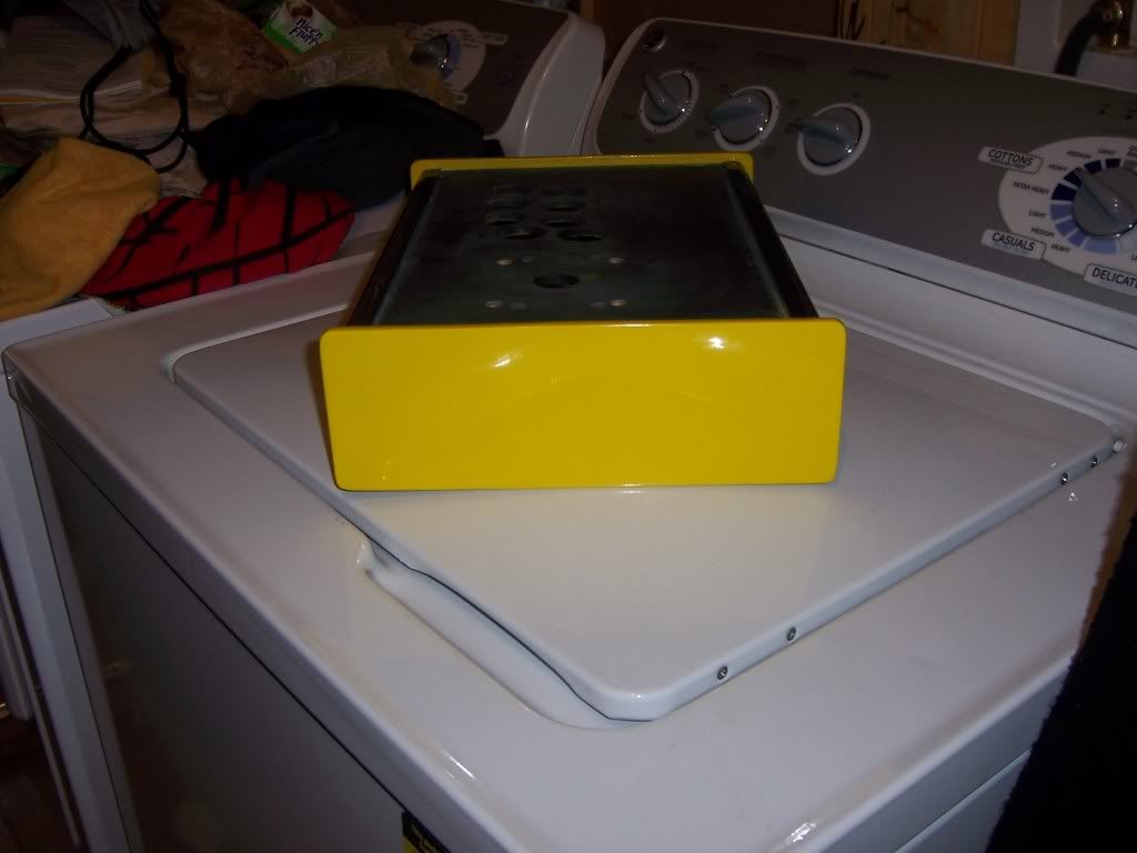
Around the middle of December, the parts for the stick started to roll in. The biggest piece of the puzzle was the case. It had been partially primed, but it looked like the primer was either dripped on or applied with an old paint roller. No matter; I needed to prime and sand it before painting anyway. The bottom of the case was simple particleboard, with 4 rubber feet screwed to them, which in turn screwed to the mounting blocks inside the case. The bottom also had a cutout for any cables that needed to run from the case. The easy thing would be to just paint the bottom blue, yellow or even black. But since I like to show off, I planned on cutting some plexiglass down to size to replace the back, much like I did with El Kabong. Flipping the case over, I took a look at the plexiglass on the top. The plexiglass is actually a fraction longer than the control panel, extending slightly into slots that were milled the sides of the case. To install, I would slightly bend the plexiglass upward, place it over the control panel, then let the plexiglass straighten out and slide into the slots. This captures the plexiglass, making it more stable. Since I had the buttons and stick, I decided to see how everything fit. The case was originally set for a JLF stick, which has a slightly different mounting plate than a JLW. Fortunately, everything still managed to line up and drop into place.
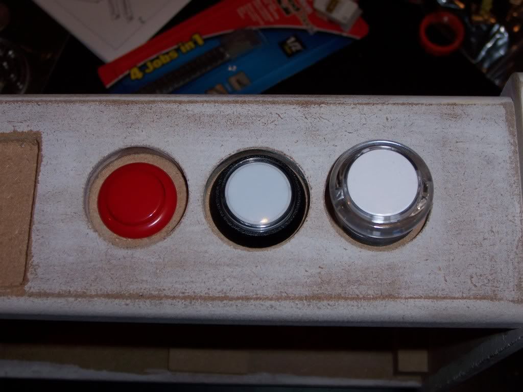
Something's missing from those buttons....
The buttons for the start, select, and home were on the rear of the case. While it’s easier to hit them on the side of the case, like El Kabong’s setup, it does make more sense from a layout standpoint when you start wiring up the buttons and pcbs. Since you have to reach to the back of the case, it also makes sure that you only hit any of those buttons when you really mean to.
That primer makes the case look ashy...
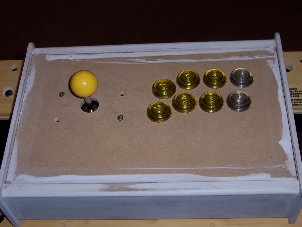
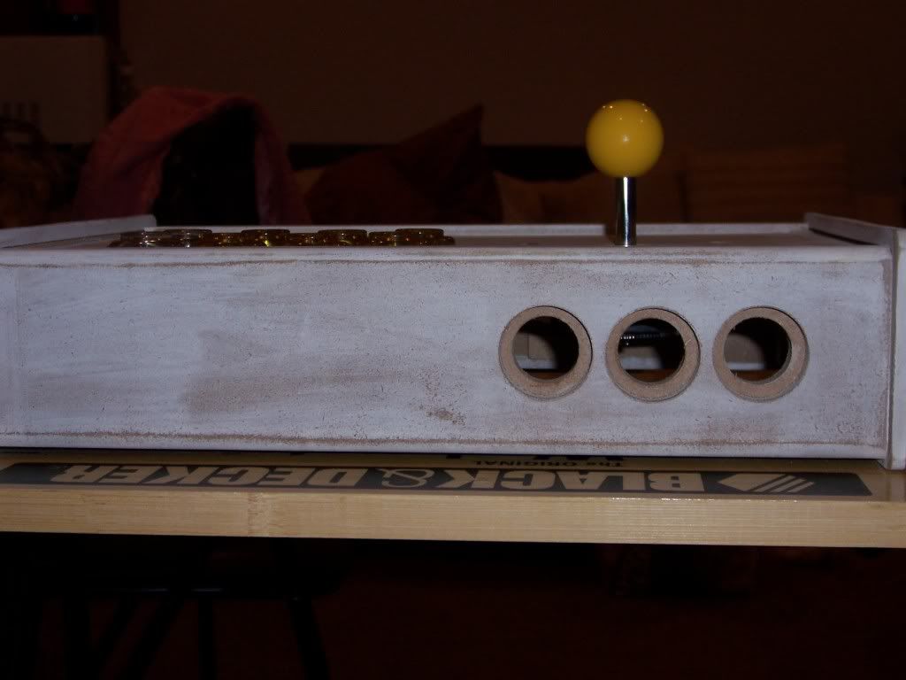
The holes were drilled out for Sanwa or Semeitsu 24mm buttons (Happ/iL doesn’t make any that size). However, when I put one of them in the hole to see how it fit, I didn’t like it. There was too much wood exposed around the rim of the button, and the holes themselves seemed too deep for such a small button. So I rummaged thru my assortment of spare parts from my last project to see what I could use as an alternative. I had picked up a lighted Happ button designed to be used in video poker games and the like just to see how it felt and if it were feasible to use as buttons on another project. It dropped in the hole without too much fuss, and didn’t have as much exposed wood around the rim. However, the button protruded much farther into the case than the Sanwa button I had, which would complicate routing the wires once everything was installed. I then grabbed the 30mm Semeitsu button I never used to get an idea how that would look. It looked like the 30mm would have the least amount of exposed wood, if any. However, I would have to widen the holes to make the buttons fit.
Like Goldilocks and the 3 bears...
That's a pretty big difference
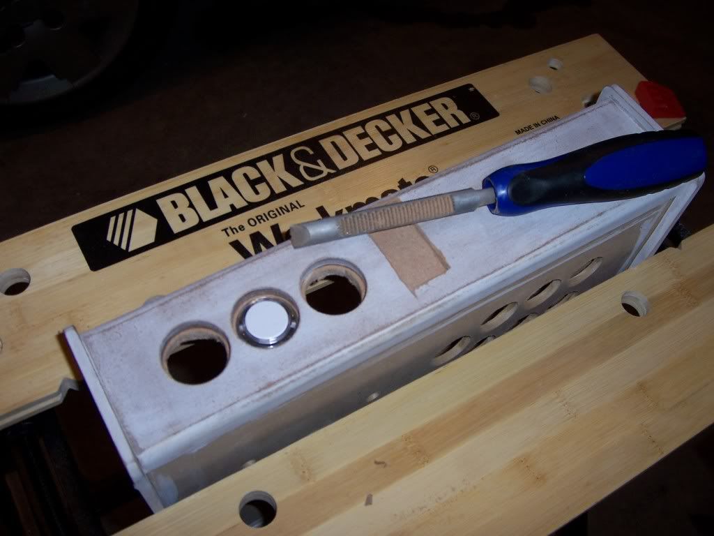
So, it was time to break out the tools. First, I put the case in my mini workbench/vise to hold the case steady. Next, I grabbed my round wood rasp, which is like an aggressive, heavy duty file. Rasps are great if you need to quickly remove or shape a piece of wood. Unlike a file, however, you only use the rasp in one direction, pushing it down or forward thru the material, instead of back and forth like a file, which would ruin the rasp. I made a few passes all the way around the hole, testing to see if it were wide enough every few passes (remember, you can take the material off, but you can’t put it back!). After about 15 minutes, I had the clearance I needed. The 30mm button filled the hole nicely and still remained below the surface of the case, making it harder to accidentally brush against it and hit the button.
Hand tools are great!
The bad thing, however, is now I had to figure out what color 30mm buttons I needed to buy. Oh well. Such is the nature of a custom stick. You could start out in one direction and end up with something completely different by time you are done.
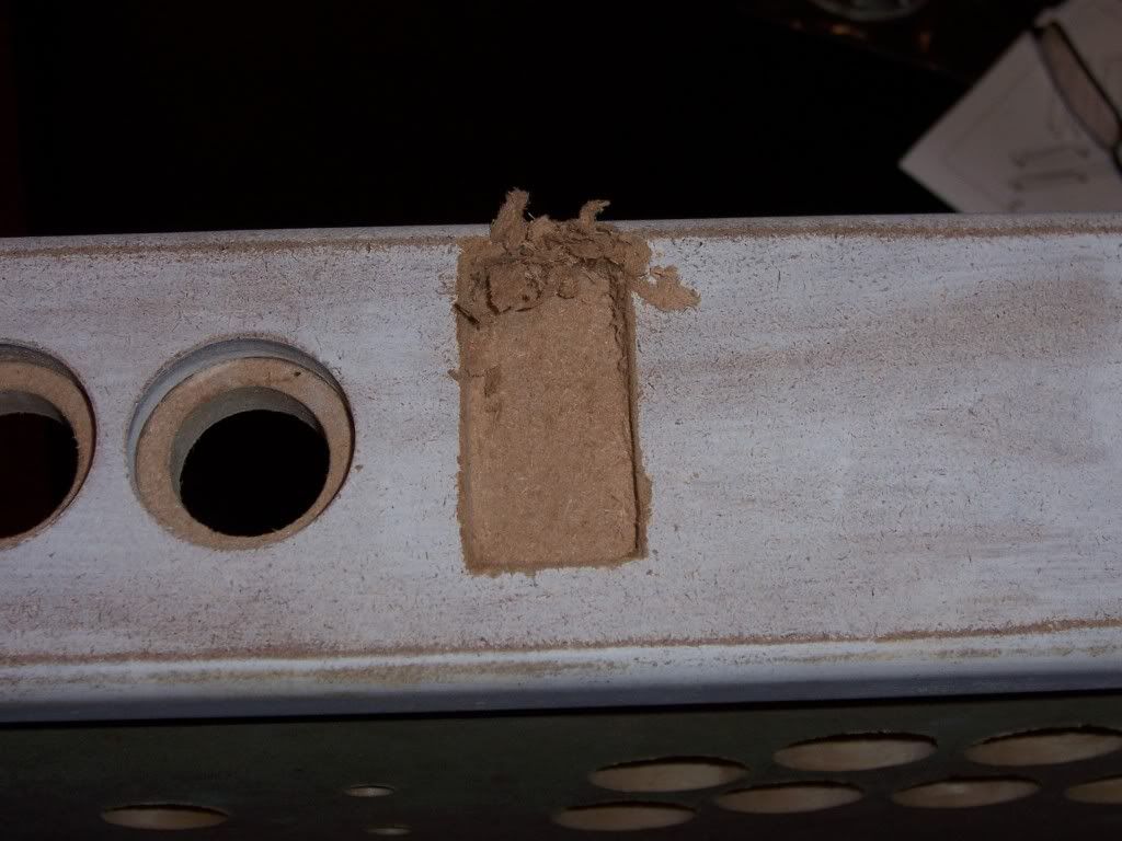
After getting the buttons sorted out, it was time to figure out what I was going to do with the switches. At first glance, the slide switches looked like they would be easier to install. But the more I looked at the case, the less likely they would work the way I wanted. The simple solution would be to mount them on an edge of the case, with the switch just slightly protruding from the bottom. Somehow that didn’t really appeal to me that much, as I feared the wiring to the switches would be a bit messy and I didn’t want the switch to be accidentally moved while playing with the case in your lap. Mounting it to the back of the case along with the start button was an option, but there wasn’t a clear way to mount the switches anywhere near flush to the back of the case. So, I put those to the side and got the rocker switches. While much bigger than the slide switches, if I mounted them on the back of the case they would have a more integrated look, whereas the exposed slide switches would look like the back of an old Atari 2600. In order to have the switches recessed similar to the buttons, I would need to chisel out a portion of the case. So, I traced a template for the two switches in a stacked position and placed it on the case. Next, I took my chisel and cut out the space. Since I’m no carpenter, you can watch this video to see how to use a chisel (a useful tool to have, I must say…)
Since I was working with what appeared to be MDF and not poplar or maple, it wasn’t very hard to cut the space out. In fact, I didn’t really need a mallet or hammer on anything other than outlining the edges. After about 20 minutes, I had the rough cut done.
It will look much neater once primed and painted
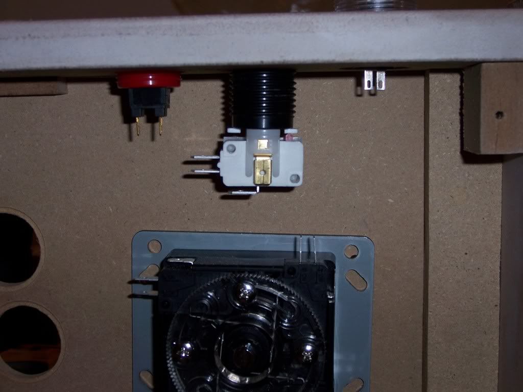
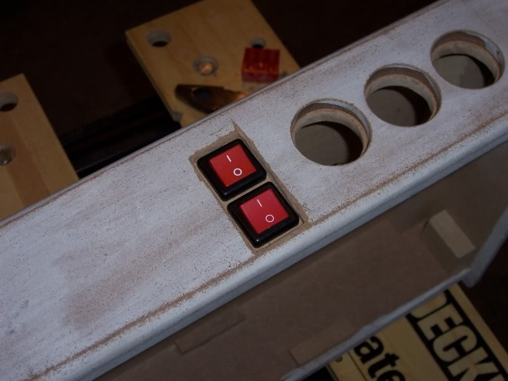
Once I had the space deep enough to my liking, I put the case back in the vise and made the holes for the body of the switch to go inside the case. I used a combination of a drill bit, my dremel and the rasp to widen and shape the holes. Afterward, I dropped the switches in to see how they looked. Success…
I wonder if I can paint them yellow...
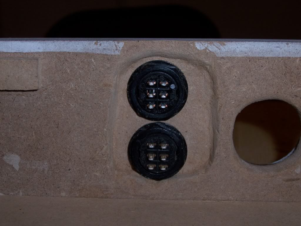
…at least until I flipped the case over, that is. Like the buttons, the switches have a locking nut that holds the switch to the case. While I had chiseled the space for the top of the switches to fit, the body of the switch didn’t protrude deep enough into the case for the locking nuts to screw on. No wonder I’ve seen the underside of other cases routed around the button holes, I thought. Ah well, more time with the chisel. Since I was working inside the case, I had limited room to position the chisel and cut out the space. But with some effort, I managed. It wasn’t as neat as the outside, but it wasn’t bad and nobody would see it anyway!
Not exactly even, but it gets the job done
In retrospect, I probably could have chiseled the front side of the case a little deeper, so that the switches were recessed more, which may have givin the needed clearance for the retaining nuts without having to work on the inside of the case. But, what's done is done. I still needed to cut the space for the USB adaptor, but at this point it hadn't come in the mail yet. Who's have thought it took so long to ship something that small from Hong Kong? No matter. The next stage of the project would take up more time than I ever expected.


