It was now time to figure out the best way to get all the PCBs in the case. As shown in Art’s Tek-Case video, there are 2 plexiglass pieces that the PCBs can mount to: one with holes drilled to fit a MCC and the other designed to zip tie a PCB to. With the case assembled, there’s just enough space to mount a PCB above and below the mount, provided you’re creative with your wire connections. The PCB mounts that attach to the support case are offset from the center line, meaning there is more space for the PCB and it’s wiring than the other side, which comes closer to the top panel of the case. Since the MCC and the Sparky Jr. would end up with the majority of the wiring, I decided to place them where they had the most room on the PCB holder. The Master$trike would only have a few wires attaching to it, so placing that one on the bottom seemed reasonable. The MadCatz Fightpad PCB, while wide, is pretty flat since it doesn’t have any analog pots to worry about. It would go on the bottom of one of the PCB holders, but I would have to figure out how to mount it to the plexiglass holder. After some mental gymnastics to figure out what would work best where, I decided to go, from left to right, top to bottom: MCC, Sparky Jr, Master$trike, Madcatz PCB.
After figuring out where to place them it was time to figure out how to mount them. While one of the PCB holders has holes drilled for the MCC, you still need to provide your own post and screws to attach the PCB to the holder. I headed down to Lowes and picked up a pack of ½” and ¾” 4-40 screws and a variety of plastic screw posts that I thought would be long enough to keep the PCB from directly touching the plexiglass holder and allow enough thread for the nut to screw on the other side. For the other PCBs, I’d need to get a bit creative. With the MCC mounted to its holder, I placed the Master$trike on the other side of the PCB holder and traces the outline of the board and it’s screw holes. Then, I removed the MCC and drilled and countersunk the holes under the MCC. That way, I could insert the screws for the Master$trike under the MCC and not worry about the screw toughing or shorting any of the MCC’s connections. I used 2 nuts on the screws: one to secure the screw to the PCB to make sure it wouldn’t get loose and as a spacer to keep the Master$trike off the plexiglass holder, and another nut to secure the Master$trike to the screw post. That setup gave me just enough clearance to attach the assembly to the top and bottom case support brackets.
The other 2 PCBs were a little trickier. Since the other PCB holder had no holes drilled at all, I would need to drill all the holes needed. I started with the Sparky Jr., tracing the board, marking the screwholes, then drilling and countersinking the holes on the opposite side of the PCB holder. The screws were mounted the same way I did for the Master$trike. The Madcatz PCB would need to have some holes drilled in the PCB, since the holes that were present weren’t spaced in a way I could use them with the plexiglass mount. I measured the width of the mount, then calculated how far apart the holes needed t be drilled on the PCB. Fortunately there is enough space on the PCB where there are no electrical traces running through it that making the holes wasn’t a huge issue. I then drilled and countersunk the holes in the plexiglass holder as I did with the other PCBs.
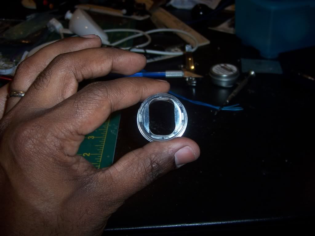
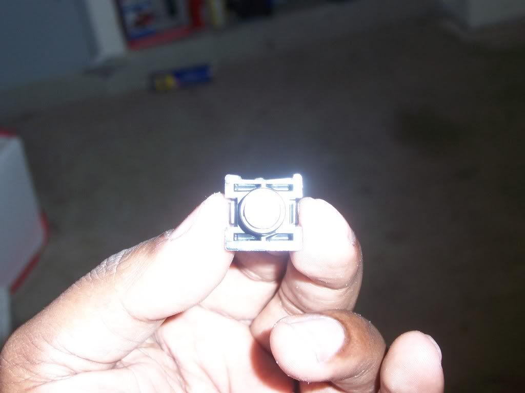
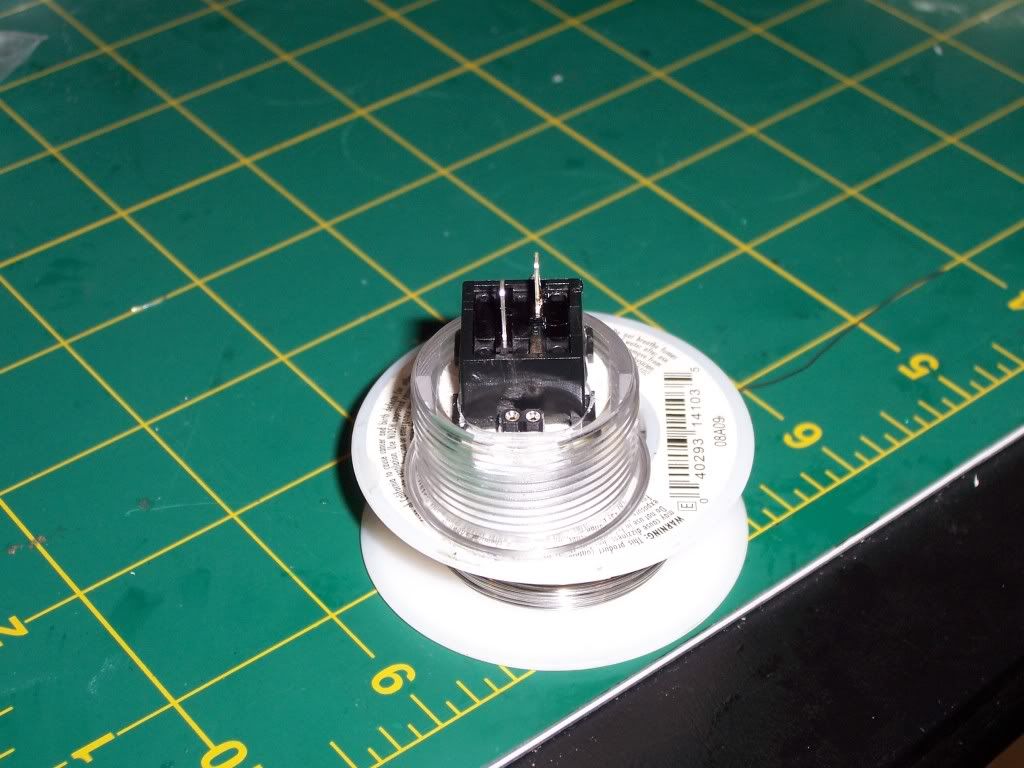
With the boards mounted and dry-fitted in the case, it was time to work on the buttons. To get the arc eyes to fit in the Seimitsu buttons, I whipped out the trusty dremel and ground out notches in the button casing to allow room to fit the pin headers that would be soldered to the arc eyes. Once that was done, I took the dremel to the sides of the switch where the pin headers would be. That way, once assembled, the headers could protrude from under the button and allow the wiring harness to plug in. I probably could have just drilled holes in the button casing and ran wires from the arc eyes and hardwired everything. But I like to be able to unplug things in case anything goes wrong, so the extra work making the pin headers fit was worth it.
Once the buttons were modified I placed them back in the case to start the arduous task of wiring everything.