I have a Black & Decker soldering iron I bought some years ago for my r/c batteries. The nice thing about the iron was it came with 2 movable clamps to act as a ‘third hand’. That way, the board and/or wires could be held in place while I maneuvered the iron and solder. But I did need to pick up a few items from Radio Shack. I purchased some rosin core solder of 2 different thicknesses and some flux paste (which was pretty invaluable and highly recommended for soldering work like this). I also picked up some desoldering braid, which I would need to remove the necessary parts from the 360 pad. The braid would soak up the melted solder from the joint like a sponge, thereby freeing the parts from the joint. Alternatively, I could have bought a desoldering bulb, which is like a vacuum that sucks up the melted solder, or desoldering iron, which has the bulb and iron together making the process a one handed affair, but the braid was sufficient (and cost effective!).
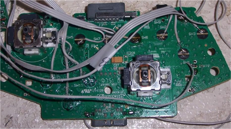
Once I got home I cracked open the 360 pad. I then carefully removed the pcb.
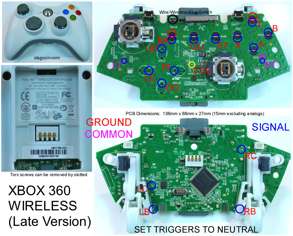
That's a lot of points to solder. Thanks Microsoft...
If you remember Gummowned’s walkthrough that I posted (and if you didn’t read my earlier post, you can find it here), there were 6 pieces that would need to be removed: the left and right triggers, the connectors for the rumble motors, and the positive and negative battery terminals. First, I plugged up the iron and let it get to the correct operating temperature. Using a brush, I dabbed a good amount of flux on the solder joint I needed to remove. Once the iron was hot, I placed the iron on one side of the joint, and the braid on the other side. After a few seconds, the flux smoked off and the solder melted, flowing into the braid. Once all of the solder was removed, the piece could be removed from the pcb. I made sure not to leave the iron on the joint for more than a few seconds. I started with the battery terminals, since the joint was not too small and there was less chance I’d screw it up. Once those came off and my confidence was up, I moved on to the connectors for the rumble motors. Those too came off with very little fuss. All that was left now were the analog triggers. The trigger pot was soldered to the pcb at 3 very small points. A few posts I had read mentioned that it was very easy to burn the contacts clean off the pcb if the iron was left on too long, damaging the board and rendering it almost useless. So I made sure to only hold the iron on the spot for 4-5 second max at a time. It slowed my progress a bit, but I was able to safely remove both of the pots and pull the trigger assemblies off with no fuss. All that was left was to use my Exacto knife and scratch off the black coating on the pads I needed to solder wires to.
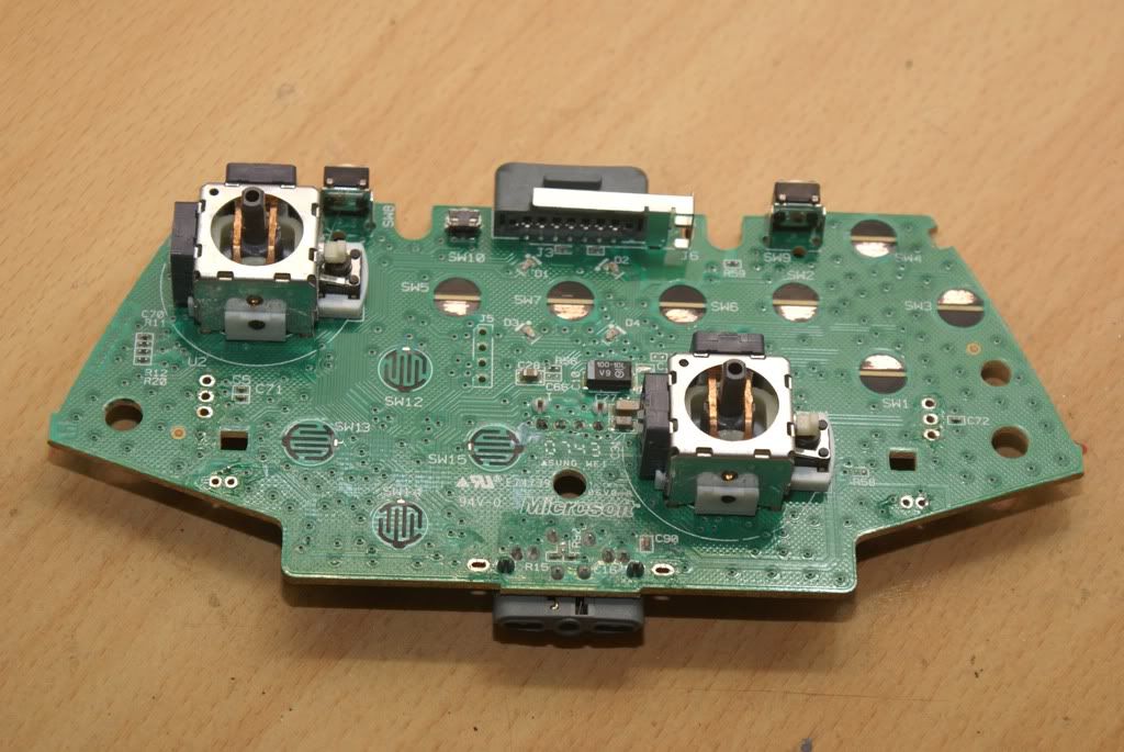
All clear. But not for long
These contacts were easy...
...these, not so much. The contacts are tiny....
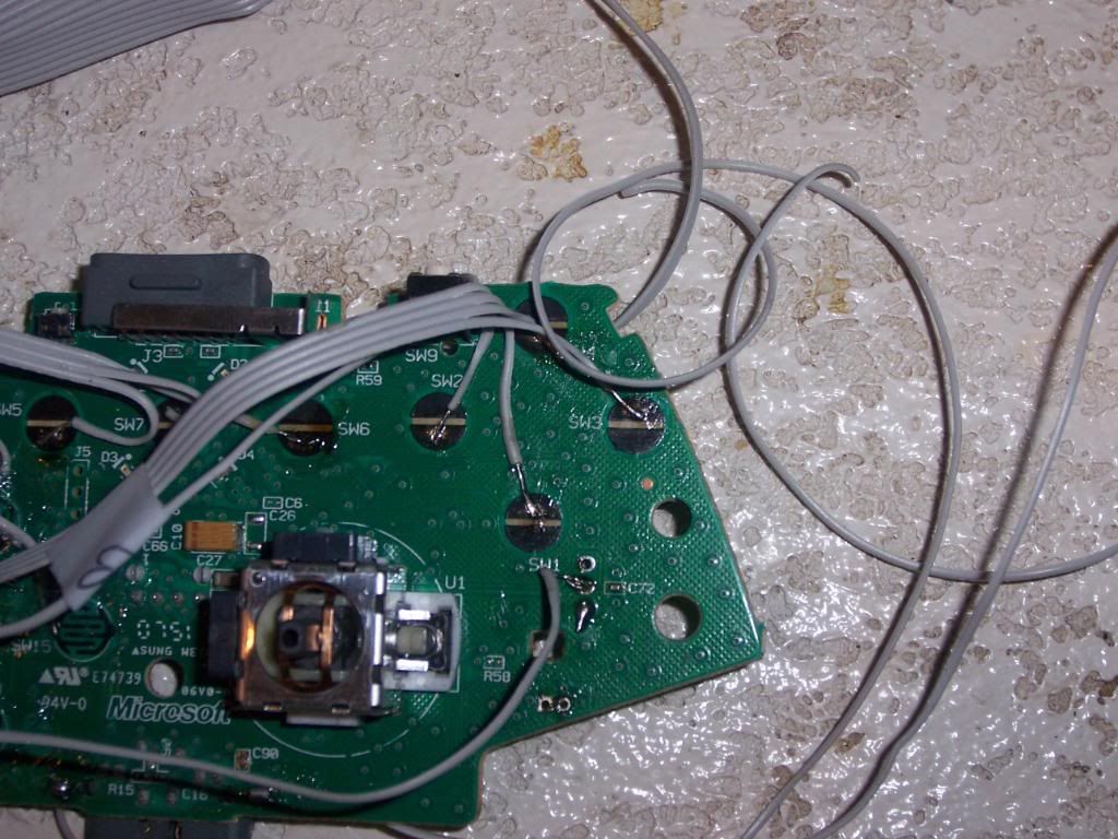
The triggers needed some special attention. In order to have them work properly, I needed to solder a 10k resistor to 2 contact points for each trigger. In addition to soldering the wire to the trigger contact point, I would need to solder an additional wire to the one of the contact points for the trigger common line (both triggers had a contact point for the common line; I just needed to tap into one). I bent the resistor into a horseshoe shape and ran the leads inside the contact points on the pcb. After they were soldered to the points, I trimmed the excess leads on the back of the pcb. With the resistors in place I then soldered the signal and common line wires to the pcb.
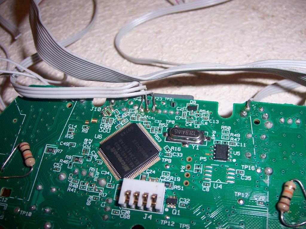
You can see the resistors and the USB connections here
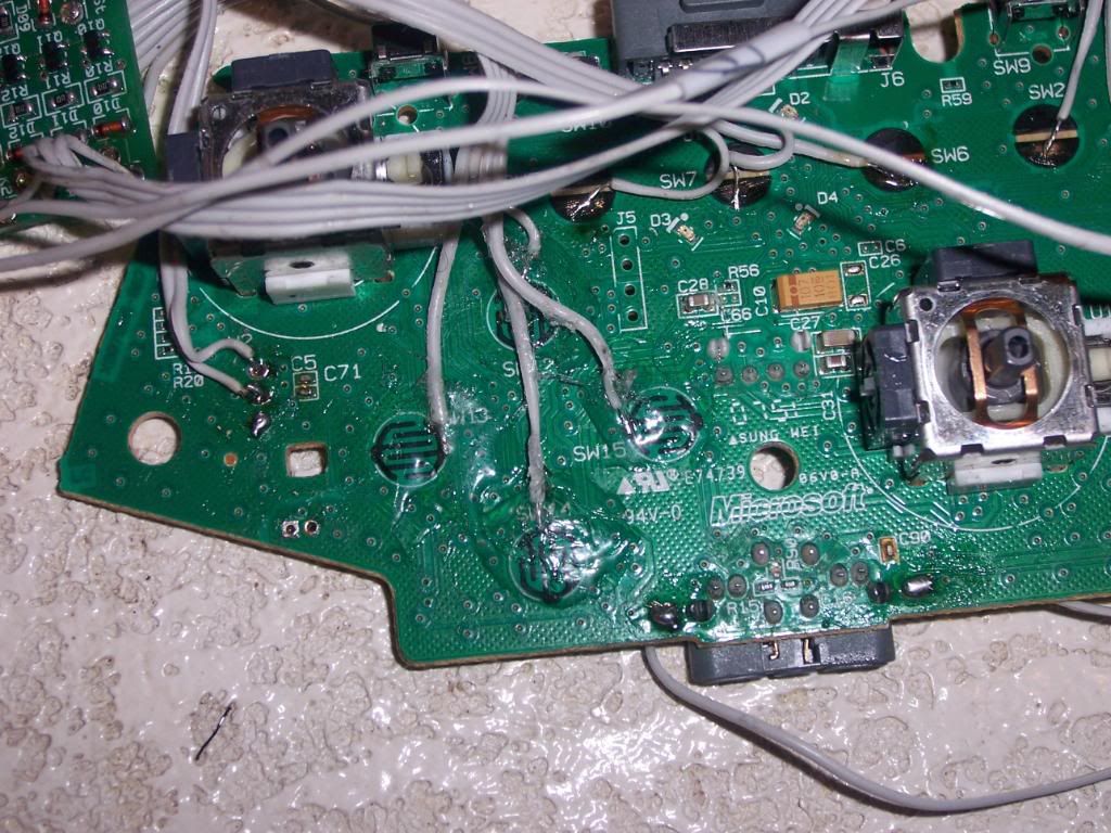
The last bit that needed to be soldered to the pcb were the wires for the usb cable. Looking at the pinout guide, I determined where the 5v (power) , D+ and D- (data) lines were for the usb. There is also a ground line, but since I had tapped into the ground (negative battery terminal) for the pcb already, I wouldn't have to worry about that. Since those points already had solder on them, this was a (relatively) simple task of heating he existing solder while the new wire was touching it, allowing the solder to melt and cool with the new wire attached. Since the points were small and close together, I took my time and made sure there was no solder that may have run over to another point on the board. At long last, the 360 pcb was 'padhacked' and ready to be connected to the leo board. Much more soldering was yet to come.
If only this was all I had to solder. But no, there is MUCH more...
No comments:
Post a Comment