LEDs (Light Emitting Diodes if you didn’t know) are wonderful things. They’re small, light, long lasting, use very little power, and can be bright as the sun (ever looked into a LED flashlight? Don’t…). People have been using LEDs on projects for years, ranging from useful, to quirky, to head-scratchingly strange to extremely nerdy. Don’t believe me? Just check this link and get back to me: 10 Stuningly Nerdy LED Projects That Are Real... Anyway, the inherent geekiness of building your own fightstick made it inevitable for people to figure out ways to cram LEDs into their custom projects. These can range from simple, such as having the lights on all the time, to slightly more involved, like having the buttons light up when you press them, to even more involved, like having 2 different colored LEDs in each button, to something much more extreme, such as designing your own custom LED board and controller to program colors, button flashes, and more. Then you have people that make dual mod, LED encrusted, robotic coffee tables like this:
Needless to say, my mod was going to be much less involved than that. That said, there was still a good amount of work that needed to be done to get this to work. First of all, you need to buy the buttons. Both Happ and Seimitsu carry translucent buttons in a variety of colors to suit your artistic need. You can even mix and match the plungers and bezels if you like for a more custom look. Next you need the LEDs. You can find these in a variety of colors, wattages and levels of brightness. You also need to purchase the correct resistors to ensure the lights don’t burn out or draw too much current from your power source. Next you have to figure out how to attach the LEDs to the buttons. Some people have run the leads for the LED in between the slot where the plunger and the bezel meet. It works, but that runs the risk of pinching the lead in between the two pieces and shorting it out. Others have taken a tiny finger drill and made holes in the bottom of the bezel, and run the wires through there, like so:

That takes patience and a steady hand
After all of that, you still need to figure out how to wire the LEDs to come on, which I’ll get to in a bit. As far as all that other craziness, I decided to take a slightly different path. Astute readers may remember I picked up the buttons from Groovy Game Gear. These buttons are designed to be used in MAME (Multiple Arcade Machine Emulator) setups (for a peek down that rabbit hole, start here). The nice thing about these buttons is that the LEDs come soldered to their own little electronic board with the appropriate resistor. The board then fits between the button and the cherry microswitch, and the LED fits into the predrilled hole at the bottom of the button. They also have nice, long leads soldered to the board to assist in wiring everything up.
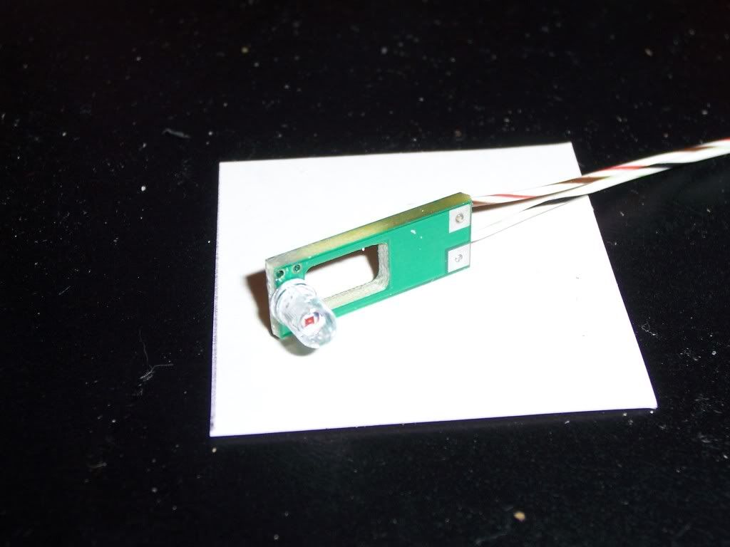
Averything in one neat package
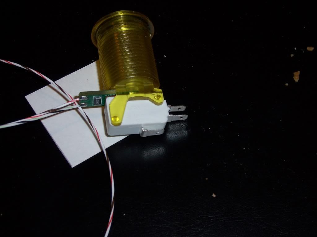
Doesn't take up more room than the button itself
The LEDs are set up to take 5 volts of current (the amount coming from the USB terminal). However, since I’m doing a wireless stick, my available voltage will be limited to what the lipo battery puts out: 3.7 volts. On the one hand, this will make the LEDs slightly dimmer than they could be. On the other hand, I wouldn’t have to worry about burning them out by supplying too much power to them. So, I took one of the assembled buttons and ran the anode and cathode (positive and negative) leads from the LED board straight to the battery to see how it would look:
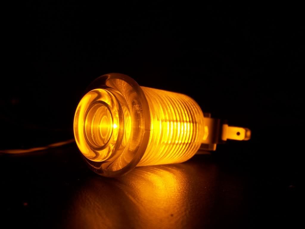
Pretty lights.....
The light was bright enough to be noticeable, but not too bright to be a distraction while playing. Considering the battery was only partially charged, I felt pretty confident the lighting would work well for this project.
With that out of the way it was time to figure out how to wire everything to make it work. Reading over the boards on SRK I came across a couple of methods to making the lights work. The easiest way by far was discovered by beneco74 (another electrical genius without whom I would never have finished this), which you can read in detail here. The wiring diagram looks something like this:

With the theory out of the way, I now had to actually get everything wired up. I installed all of the buttons with the LED boards and switches in place so I could figure out which direction I needed to turn the buttons to make routing the wires easier. One concern I had was how this would work if I ever needed to replace any of the components (LED board, bad switch, buttons, etc). Instead of soldering the cathodes directly to the switch or directly to the wiring harness, I decided to use female quick disconnects on all the LED cathodes. I could then connect 2 wires to each quick disconnect for the signal harness: one that would run from the button to the leo PCB, and a shorter wire with a male quick disconnect to connect to the female quick disconnect on the LED cathode. Initially, I decided to run all of the anodes to a junction block, wiring 4 to each terminal and using a jumper wire to connect all 8 together, then using another jumper wire to connect them to the battery. All I would need then would be to make a ground chain for the switches and the lights should work.
Setting up the cathodes was pretty simple. I cut each of the cathode leads on the LED boards down to about an inch and soldered a female .187” connector to it. Quick disconnects are made so you can simply crimp the ends to the wire, eliminating the need to solder them. But, I wanted to make sure the connection wouldn’t come loose after I delivered the finished product. After that, I decided to tackle the ground chain. I took a piece of the leftover wire from the cathode lead and soldered on a female .187” connector. I slid the other end through a thin piece of cable sleeving I had, then connected it to the ground on the switch. Next I stretched the sleeved cable over to the next switch to figure out how long the wire needed to be in the chain. Once I determined the length needed, I pulled the wire thru the sleeving and trimmed it close to the switch. Next I took another piece of wire, slid one end back thru the cable sleeving and twisted the other end together with the first piece of wire. Then I soldered the connector on the two wired and connected it to the ground of the switch. I then repeated the tedious process for the next 6 buttons. The last wire in the chain I left free, since that would be connected with the battery ground. With that finished, it was time to work on the signal harness. First, I pulled off one long strand of wire from the IDE cable and cut it into 8 pieces, each about 1 ½ inches long, and soldered a male .187” connector to each. Next, I grabbed some more IDE cable and pulled off a long 8 wire section. I split one end of the cable about ¼ of the way down the middle, with 4 wires on each side. Starting with the 2 buttons closest to the edge of the case, I pulled one wire free from each side of the IDE cable and stripped the ends. I twisted one of the wires with the male connector on each end of the wires from the IDE ribbon. Then I soldered on a female connector to each. Now I could connect the harness to the signal tab on the switch and connect the male and female connectors of the cathodes together. Once I finished those 2 buttons, I pulled off 2 more strands from the IDE cable and trimmed them close to the set of buttons and repeated the process until all 8 buttons were wired. To make sure that all my connectors were soldered properly, I connected the anodes to a junction block as I described earlier, and connected the ground chain to another spot on the junction block. I then ran 2 wires from the junction block to the battery.
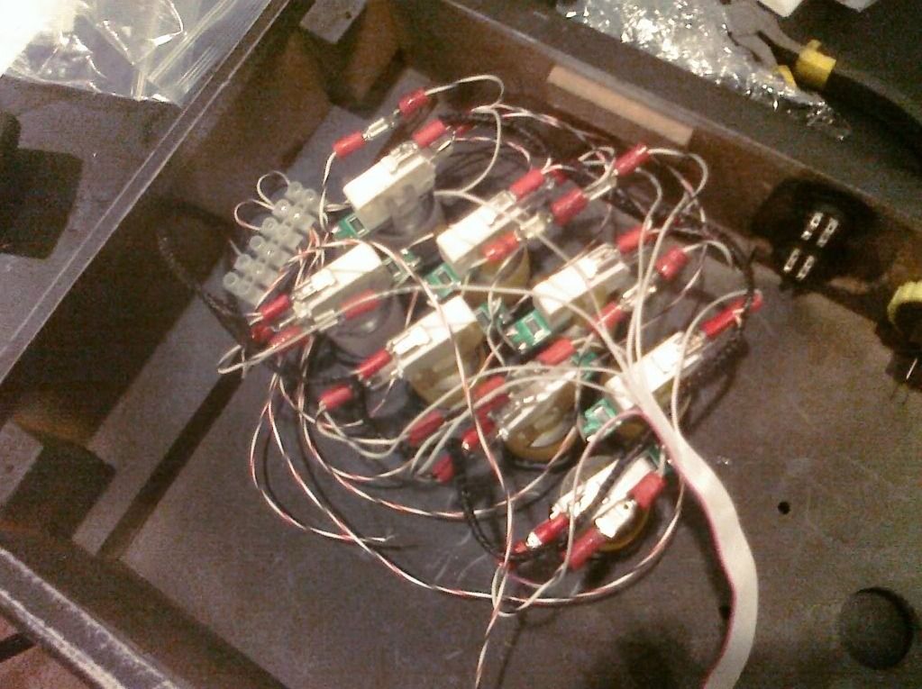
That is a LOT of wire. And I'm just getting started...
To my surprise and glee, the buttons worked as promised, lighting up nicely whenever the button was pressed, even if more than one button was pressed at a time. Since the wires looked a bit ungainly I ran the anode leads through another piece of cable sleeving, allowing me to route the leads closer to the buttons and making everything look neater. The whole process took much longer than I anticipated, but it was nice to know that my plan would actually work. That said, there was still an enormous amount of soldering and wiring that I had to do before I was any where close to being done. I still had to solder the 360 PCB to the leo, solder the signal wire harness from the buttons to the leo, solder and wire signal harnesses and ground chains for both the joystick and the start/select/home buttons, solder wires from the USB points from both the 360 PCB and the PS3 PCB to the switches, and wire up a USB cable from the switches to the USB adaptor, which still hadn’t come in the mail. Daunting, to say the least. However, the Vikings/Cowboys game was on, and my red plastic cup was in need of an adult beverage. So I called it a day and watched Favre do his rendition of ‘Pants On The Ground’ …
No comments:
Post a Comment